Comparison of Heat Exchanger Types
Heat Transfer Engineering
Heat Exchanger Knowledge
Counter & Parallel Flow Heat Exchanger Calculator
Each of the three types of heat exchangers (Parallel, Cross and Counter Flow) has advantages and disadvantages. But of the three, the counter flow heat exchanger design is the most efficient when comparing heat transfer rate per unit surface area. The efficiency of a counter flow heat exchanger is due to the fact that the average T (difference in temperature) between the two fluids over the length of the heat exchanger is maximized, as shown in Figure 4 Counter Flow. Therefore the log mean temperature for a counter flow heat exchanger is larger than the log mean temperature for a similar parallel or cross flow heat exchanger. (See the Thermodynamics, Heat Transfer, and Fluid Flow Fundamentals for a review of log mean temperature). This can be seen by comparing the graphs in Figure 3, Figure 4, and Figure 5. The following exercise demonstrates how the higher log mean temperature of the counter flow heat exchanger results in a larger heat transfer rate.
The log mean temperature for a heat exchanger is calculated using the following equation.
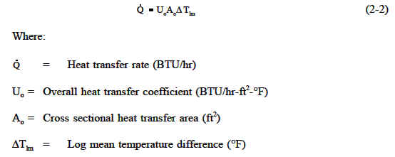
Heat transfer in a heat exchanger is by conduction and convection. The rate of heat transfer, "Q", in a heat exchanger is calculated using the following equation.
Consider the following example of a heat exchanger operated under identical conditions as a counter flow and then a parallel flow heat exchanger.
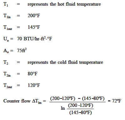

Inserting the above values into heat transfer Equation (2-2) for the counter flow heat exchanger yields the following result.
Inserting the above values into the heat transfer Equation (2-2) for parallel flow heat exchanger yields the following result.
The results demonstrate that given the same operating conditions, operating the same heat exchanger in a counter flow manner will result in a greater heat transfer rate than operating in parallel flow.
In actuality, most large heat exchangers are not purely parallel flow, counter flow, or cross flow; they are usually a combination of the two or all three types of heat exchangers. This is due to the fact that actual heat exchangers are more complex than the simple components shown in the idealized figures used to depict each type of heat exchanger. The reason for the combination of the various types is to maximize the efficiency of the heat exchanger within the restrictions placed on the design. That is, size, cost, weight, required efficiency, type of fluids, operating pressures, and temperatures, all help determine the complexity of a specific heat exchanger.
One method that combines the characteristics of two or more heat exchangers and improves the performance of a heat exchanger is to have the two fluids pass each other several times within a single heat exchanger. When a heat exchanger's fluids pass each other more than once, a heat exchanger is called a multi-pass heat exchanger. If the fluids pass each other only once, the heat exchanger is called a single-pass heat exchanger. See Figure 6 for an example of both types. Commonly, the multi-pass heat exchanger reverses the flow in the tubes by use of one or more sets of "U" bends in the tubes. The "U" bends allow the fluid to flow back and forth across the length of the heat exchanger. A second method to achieve multiple passes is to insert baffles on the shell side of the heat exchanger. These direct the shell side fluid back and forth across the tubes to achieve the multi-pass effect.

Heat exchangers are also classified by their function in a particular system. One common classification is regenerative or nonregenerative. A regenerative heat exchanger is one in which the same fluid is both the cooling fluid and the cooled fluid, as illustrated in Figure 7. That is, the hot fluid leaving a system gives up its heat to "regenerate" or heat up the fluid returning to the system. Regenerative heat exchangers are usually found in high temperature systems where a portion of the system's fluid is removed from the main process, and then returned. Because the fluid removed from the main process contains energy (heat), the heat from the fluid leaving the main system is used to reheat (regenerate) the returning fluid instead of being rejected to an external cooling medium to improve efficiency. It is important to remember that the term regenerative/nonregenerative only refers to "how" a heat exchanger functions in a system, and does not indicate any single type (tube and shell, plate, parallel flow, counter flow, etc.).
In a nonregenerative heat exchanger, as illustrated in Figure 7 below, the hot fluid is cooled by fluid from a separate system and the energy (heat) removed is not returned to the system.

Link to this Webpage:
© Copyright 2000 -
2024, by Engineers Edge, LLC
www.engineersedge.com
All rights reserved
Disclaimer |
Feedback
Advertising
| Contact