Related Resources: heat transfer
Heat Transfer Printed Circuit board with Components Equation
Heat Transfer Engineering
Thermodynamics
Engineering Physics
Forced Convection Heat Transfer Printed Circuit board with Components Equation and Calculator
Equation and calculator to determine the heat transfer coefficient and temperature of a PCB board with components. Components are assume to be isothermal blocks. Temperatures at each row of components is calculated for the specified conditions.
Calculator on "To Do" list...
The conductance should be less than 0.03 W / °C. In this model each component and the surrounding PCB area is treated in isolation, the PCB area being the rectangle formed cutting midway between components. It is then assumed that the heat that is dissipated by this isolated component and area of PCB is equal to the component power. The heat path is by convection from the exposed surfaces and conduction through the leads and stand-off gap into the PCB and then convection from the PCB to the air.
Tube wall temperature (Tw ) is calculated as:
Tc = Tl + q R
Ambient air temperature is calculated from:
Tl = Ta +Qt / (F · ρ · Cp )
Total heat dissipated upstream from the component Qt is calculated as:
Qt = q · M · (N - 1)
Flow rate F can be calculated as:
F = um · a
Flow area a is calculated as:
a = Wb · HF - (M · S · e)
Ri calculated as:
Ri = 1 / (h · A1 + 1 / ( Ri + 1/ (A2 · h) ) )
Exposed surface area A1 is calculated as:
A1 = S · b + 2e (S + b)
Thermal interface resistance Ri can be calculated as:
Ri = 1 / ( (1/rc ) + (1 / rl ) )
rc and rl can be calculated as:
rc = del / (ka · S · b)
rl = L / (kl · n · Al )
The d x w rectangles of the PCB are not isothermal and therefore the effective area of the component A2 is calculated as:
A2 = 2 ( d' · w' ) - S · b
d' is the effective streamwise pitch and w' is the effective lateral width, which are calculated as:
w' = E1 · w + S ( 1 - E1 )
d' = E2 · d + b ( 1 - E2 )
d is the component width and E1 and E2 are the two PCB fin efficiencies in the lateral and streamwise directions respectively. These are calculated as follows:
E1 = ( tanh M1 ) / M1
E2 = ( tanh M2 ) / M2
where:
M1 = ( ( w - S ) / 2 ) ( 2 h / C1 ) 0.5
M2 = ( ( d - b ) / 2 ) ( 2 h / C2 ) 0.5
Conductance of the PC Board is calculated as:
C1 = kb · t + kc · φ1
C2 = kb · t + kc · φ2
Depending on flow velocity um , the heat transfer coefficient is be calculated using Will's Correlation when the flow velocity is between or equal to 0.2 and 8.0 m/s
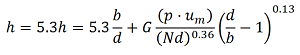
Where G is 6.2 when no card guides are used at the PCB leading edges and 7.6 when chard guides are not used.
The conductance of the PC Board is calculated as (both lateral as well as streamwise):
C = kb · tb + kc · φ
Where kb is the conductivity of the board without copper, tb is the thickness of the board without copper, kc is the conductivity of the copper used, and φ is the ratio of the volume of copper on the PC Board in the direction of interest per unit plan area of pcb.
Where:
Ta = Ambient Temperature @ entrance (°C)
Tc = Component Temperature (°C)
Tl = Local Ambient Temperature (°C)
q = Heat Load per. Component (W)
R = Overall Thermal Reisistance (°C/W)
Ri = Internal Resistance (°C/W)
rc = Resistance across Air Gap (°C/W)
rl = Resistance across Leads (°C/W)
Qt = Total heat dissipated upstream of the component (W)
F = Flow Rate (m3/s)
ρ = Density of Fluid (kg/m3)
Cp = Specific Heat Air (J/(kg·°C))
Qt = Total Heat Dissipated Upstream (W)
q = Heat Load per. Component (W)
M = Number of Components Lateral to Flow
N = Number of Components Parallel to Flow
L = Length of Leads (m)
um = Average flow velocity in free flow area between boards (m/s)
a = Flow Area per PCB (m2)
Wb = Width of PCB (m)
HF = Height of Flow Channel (m)
S = Width Lateral to Flow (m)
e = Protruding to Flow (m)
b = Component Length Parallel to Flow (m)
d = Component Width (m)
w = Pitch Lateral to Flow(m)
h = Heat Transfer coefficient (W/m2 - °C)
A1 = Exposed Surface Area m2
A2 = Effective Area m2
del = Air Gap between PCB and Component (m)
ka = Thermal Conductivity of Air (W/m - °C)
kb = Thermal Conductivity of Board (W/m - °C)
kc = Thermal Conductivity of the copper used on Board (W/m - °C)
kl = Thermal Conductivity of Leads (W/m - °C)
t = Thickness of Board (m)
n = Number of Leads
d' = Effective Streamwise Pitch (m)
w' = Effective Lateral Width (m)
E1 = Efficiencies of Fin Lateral
E2 = Efficiencies of Fin Streamwise
C1 = Conductance of PC Board Lateral (W/m - °C)
C2 = Conductance of PC Board Streamwise (W/m - °C)
φ1 = Volume of copper per area of PCB (Lateral to Flow) (m3/m2)
φ2 = Volume of copper per area of PCB (Parallel to Flow) (m3/m2)
Related:
- Thermal Conductivity of Fluid (W/m - °C)
- Dynamic Viscosity (kg/m-s)
- Dynamic Viscosity (kg/m-s)
- Reynolds number
- Prandtl number
- Nusselt Number
- Heat transfercoefficient (W/m2 - °C)
References
Thermal Analysis of Aircooled PCB's , Electronic Production, Parts 1 - 4, May - August 1983.
Rajaram, Dr. S., Thermal Design of Electronic Equipment For Reliability & Performance , AT&tbell Laboratories, Whippany USA. Sess. 3 p 20 - 42.
Link to this Webpage:
© Copyright 2000 -
2024, by Engineers Edge, LLC
www.engineersedge.com
All rights reserved
Disclaimer |
Feedback
Advertising
| Contact