Shear Stress Equations and Applications
Shear Stress Equations and Applications
General shear stress:
The formula to calculate average shear stress is
- τ = the shear stress;
- F = the force applied;
- A = the cross-sectional area of material with area perpendicular to the applied force vector;
Beam shear:
Beam shear is defined as the internal shear stress of a beam caused by the shear force applied to the beam.

- V = total shear force at the location in question;
- Q = statical moment of area;
- t = thickness in the material perpendicular to the shear;
- I = Moment of Inertia of the entire cross sectional area.
This formula is also known as the Jourawski formula.
Semi-monocoque shear:
Shear stresses within a semi-monocoque structure may be calculated by idealizing the cross-section of the structure into a set of stringers (carrying only axial loads) and webs (carrying only shear flows). Dividing the shear flow by the thickness of a given portion of the semi-monocoque structure yields the shear stress. Thus, the maximum shear stress will occur either in the web of maximum shear flow or minimum thickness.Also constructions in soil can fail due to shear; e.g., the weight of an earth-filled dam or dike may cause the subsoil to collapse, like a small landslide.Impact shear. The maximum shear stress created in a solid round bar subject to impact is given as the equation:
"Jourawski formula"
2 (U G / V )(1/2)
whereU = change in kinetic energy;
G = shear modulus;
V = volume of rod;
and
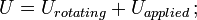
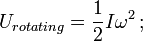
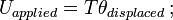
 = mass moment of inertia;
ω = angular speed.
Shear stress in fluids:
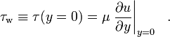
Any real fluids (liquids and gases included) moving along solid boundary will incur a shear stress on that boundary. The no-slip condition dictates that the speed of the fluid at the boundary (relative to the boundary) is zero, but at some height from the boundary the flow speed must equal that of the fluid. The region between these two points is aptly named the boundary layer. For all Newtonian fluids in laminar flow the shear stress is proportional to the strain rate in the fluid where the viscosity is the constant of proportionality. However for Non Newtonian fluids, this is no longer the case as for these fluids the viscosity is not constant. The shear stress is imparted onto the boundary as a result of this loss of velocity. The shear stress, for a Newtonian fluid, at a surface element parallel to a flat plate, at the point y, is given by:
- μ is the dynamic viscosity of the fluid;
- u is the velocity of the fluid along the boundary;
- y is the height above the boundary.
In case of wind, the shear stress at the boundary is called wind stress.
1. Timoshenko, Stephen P. (1983), History of Strength of Material, Courier Dover Publications, p. 141, ISBN 0486611876, http://books.google.com/?id=tkScQmyhsb8C .
2. Day, Michael A. (2004), The no-slip condition of fluid dynamics, Springer Netherlands, pp. 285–296, ISSN (Print) 1572-8420 (Online) 0165-0106 (Print) 1572-8420 (Online), http://www.springerlink.com/content/k1m4t1p02m778u88/.
3. Naqwi, A. A.; Reynolds, W. C. (jan 1987), "Dual cylindrical wave laser-Doppler method for measurement of skin friction in fluid flow", NASA STI/Recon Technical Report N 87
4. Große, S.; Schröder, W. (2009), "Two-Dimensional Visualization of Turbulent Wall Shear Stress Using Micropillars", AIAA Journal 47 (2): 314–321, Bibcode 2009AIAAJ..47..314G, doi:10.2514/1.36892
5. Große, S.; Schröder, W. (2008), "Dynamic Wall-Shear Stress Measurements in Turbulent Pipe Flow using the Micro-Pillar Sensor MPS³", International Journal of Heat and Fluid Flow 29 (3): 830–840, doi:10.1016/j.ijheatfluidflow.2008.01.008
Link to this Webpage:
© Copyright 2000 -
2024, by Engineers Edge, LLC
www.engineersedge.com
All rights reserved
Disclaimer |
Feedback
Advertising
| Contact