GD&T Two Mating Diameters Tolerance Analysis at MMC Calculator
Tolerances, Engineering Design & Limits & Fits
Geometric Dimensioning & Tolerancing GD&T Training
(This calculator requires a java - enabled browser)
GD&T Two Mating Diameters Tolerance Analysis at MMC Calculator | GD&T Training
This calculator calculates position tolerances utilizing principles and concepts withinASME Y14.5-2009 and ASME Y14.5 - 2018, Geometric Dimensioning and Tolerancing (GD&T).
Open
GD&T Two Mating Diameters Tolerance Analysis at MMC Calculator
See application at bottom of page.
This calculator will calculate the required field for the given condition. Calculations assume a line-line case with "Clearance = 0" or will compensate for a static clearance as defined.
Note: All fields require an input except field being calculated.
Four (6) inputs are required.
See the
application illustration at bottom of page.
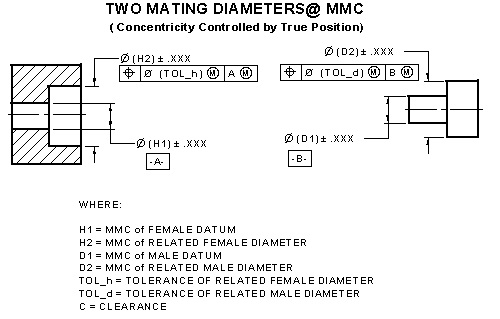
The following are definitions for the elements:
Hole Diameter H2- This is the smallest hole (MMC) or similar other feature of size.
Hole Tolerance Tol_h - This is the positional tolerance for the given feature of size.
Hole Size (Datum) H1 - This is the smallest hole (MMC) for the given feature of size.
Shaft Diameter D2- This is the largest size (MMC) of the shaft or other feature of size.
Shaft Tolerance Tol_d - This is the positional tolerance for the given feature of size.
Shaft Size (Datum) D1 - This is the largest shaft (MMC) for the given feature of size.
Clearance C - This is additional clearance required
for design when line-line worst case condition is
not desired.
Open
GD&T Two Mating Diameters Tolerance Analysis at MMC Calculator
Click on the below image to enlarge
Related Resources:
Link to this Webpage:
© Copyright 2000 -
2024, by Engineers Edge, LLC
www.engineersedge.com
All rights reserved
Disclaimer |
Feedback
Advertising
| Contact