What are the Advantages using Geometric Dimensioning and Tolerancing GD&T
What are the Advantages using Geometric Dimensioning and Tolerancing GD&T?
ASME Y14.5 - 2009 geometric dimensioning and tolerancing ( GD&T ) is a language of symbols used on mechanical drawings to efficiently, and accurately communicate geometry requirements for features on parts and assemblies. GD&T is, and has been, successfully used for many years in the automotive, aerospace, electronic and the commercial design and manufacturing industries. GD&T, both ASME Y14.5 - 2009 and Geometrical Product Specifications ISO 1101 and derivatives are the only recognized international drawing standards in use throughout the world. See "Quick Guide - Differences between ASME Y14.5-2009 and ISO 1101 GD&T"
What are the Advantages?
In today'smodern and technically advanced design, engineering and manufacturing world, effective communication is required to ensure the design and manufacture of successful products. Success oriented organizations, which require accurate and common lines of communications between engineering, design, manufacturing, and quality should consider (GD& T) as their mechanical drawing standard. Some distinct advantages of GD&T are as follows:
GD&T facilitates an efficient means to communicate specific datum'son a part. A datum is just a fancy word for saying which specific feature on a part will be used as a reference (zero) for tolerance calculations, dimensional measurement, and most importantly, from where the feature(s) manufacturing should build from to ensure a consistent part. Without the use of a datum system (zero reference) on a part, it is not clear to manufacturing or quality where to manufacture or measure from. Additionally, the use of datum'sdramatically simplifies the design and specification of fixtures for use in manufacturing and quality verification steps.
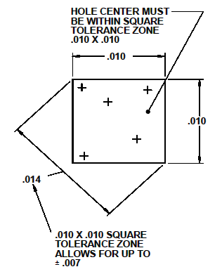
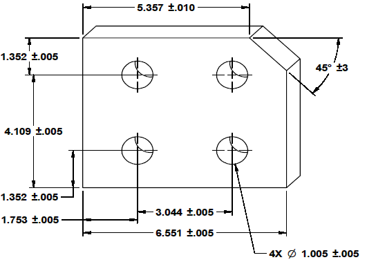
GD&T allows the use of round tolerance zones as opposed to square or rectangular tolerance zones as given by limit tolerancing methods for cylindrical (holes, shafts) features. In the mechanical drawing given in figure 1, there are four holes drilled thru the block, and each holes location relative to each other and the edges are specified using a limit tolerance of a distance and +.005 and -.005. This means the derived center of each of the holes must fall within a square tolerance zone .010 x .010 at some location, which as illustrated in figure 2.
Figure 1

Figure 2
In figure 2, there is a dimension attached to the top left and bottom right corners. This is the actual worst scenario for which the hole features may be manufactured (.014 or + .007 and -.007). Therefore, a square tolerance zone defined at +.005 and -.005 is actually +.007 and -.007 worst case. Assuming the that this part must be interchangeable, or always fits in the target assembly when manufactured as specified above, then the +.007 and -.007 is the real worst case scenario (not +.005 -.005).
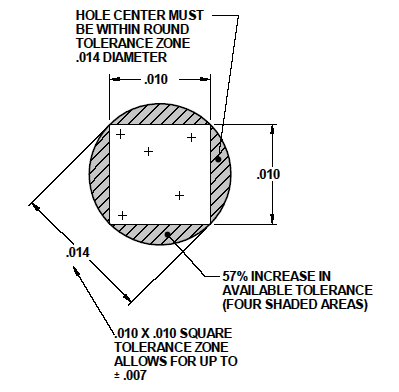
In geometric dimensioning and tolerancing, cylindrical features may be located with round or cylindrical tolerance zones. Round tolerance zones offer several distinct advantages over square or rectangular tolerance zones. In figure 3, we have overlaid a round tolerance zone over our square tolerance zone for the part given in Figure 1. The shaded areas represent the increase in tolerance available by using round tolerance zone equivalent to the specified square tolerance zone in figure 1. As you can see, the hole may now be manufactured within the shaded areas where the square tolerance zone ends to the right, left, top, bottom at .007 off perfect center. This increase in available tolerance is equal to approximately 57%. A round tolerance zone is simply less expensive to manufacture, additionally GD&T allows for material modifiers, which allow for up to several hundred percent increase in tolerance, reducing manufacturing difficulty even more while maintaining interchangeability requirements. Additionally, because the tolerance zones are round this allows the specification of similar features (round pin for a hole) on quick check tools, such as go and no-go fixtures, where with square or rectangular tolerance zones, the verification tool requirements are not clear.

Figure 3
Note: Applying one of the fourteen geometric characteristics defined within ASME Y14.5 2009 GD&T, is not always required, or the best approach for defining feature requirements on a mechanical drawing. The ASME standard does include requirements for limit tolerancing techniques. Regardless of industry or application requirements, ASME Y14.5 2009, GD&T is a great mechanical drawing standard, and is recognized throughout the world.
Where'sthe Money, How do we Save?
The above are only two examples of how GD&T improves communication, reduces manufacturing cost, and simplifies inspection. Actual savings realized by an organization migrating to GD&T on mechanical drawings will vary depending many factors, some examples are:
- Engineering and Manufacturing Team Size
- Complexity of Parts
- Mechanical Drawing Release Cycle Requirements
- Production Requirements (Few or Many Parts)
- Organization Internal or External Manufacturing Facilities
Case study:
Internal machine shop contacts engineering and design to arrange meeting to discuss confusing mechanical drawing requirements. Cost impact as follows:
Personnel Meeting |
Time Charged or Consumed (hours) |
Engineer |
1 |
Designer |
1 |
Program Manager |
1 |
Machine Shop Lead |
1 |
Responsible Machinist |
1 |
Total Time |
5 Hours |
Resulting Manpower Impacts:
| Action | Time Charged or Consumed (hours) |
| Engineering Drawing Change | 8 |
| Engineer Review | 1 |
| Signature Cycle | 2 |
| Total Time | 11 Hours |
Infrastructure Costs:
| Action | Estimated Cost ($$) Based on Industry |
| Processing Mechanical Drawing within document control. Includes document image reproduction, and archival and storage. | $500 - $2,000 (Depends on industry and organizational requirements). Big aerospace represents the high end. |
| Document redistribution and processing by Manufacturing | $50 |
| Total | $550 $2,500 |
Total cost impact (conservative):
| Action | Cost |
| Personnel Meeting | 6 hours @ $70/hour = $420 |
| Updating Mechanical Drawing | 11 hours @ $70/hour = $770 |
| Document Control | $500 or $2000 |
| Document Reproduction / Distribution | $50 |
| Total Impact | $1740 or $3240 |
The case study above is a common miscommunication scenario where an organization has not established or trained for a mechanical drawing standard. Other common impacts are:
- Part rejections due to difficult tolerance requirements (round vs. square tolerance zone).
- Parts not interchangeable and being scraped.
- Inability to use best available industry quote due to vendor challenges with non-standard mechanical drawings.
- Schedule impacts due to any of the above reasons
Training all relevant personnel to the mechanical drawing industry standard (geometric dimensioning and tolerancing) will reduce confusion, increase available tolerance, and save time and money. Organization / industry (space / aerospace) studies, which I have participated within as a team member, have demonstrated a reduction in engineering and manufacturing change (change notices) at almost twelve percent following training, and full integration of geometric dimensioning and tolerancing per ASME Y14 .5 - 2009.
Who should be trained in Geometric Dimensioning and Tolerancing?
Engineering, design, drafting, quality, dimensional inspection, and manufacturing should be trained to interpret, and as appropriate for their profession, apply GD&T. All of these professions utilize drawing interpretation and application knowledge to execute their responsibilities. Parts and procurement personnel should have some knowledge of GD&T to understand how to process a mechanical drawing for quote. Training personnel in the interpretation and application of GD&T will effectively reduce product design to market time, and production costs.
Kelly Bramble
ASME Certified Senior GDTP
Last updated: August 28, 24 2013
