Related Resources: calculators
Bolt Spacing Tolerance Analysis Formula and Calculator
Mechanical Tolerance Analysis, Specification and Calculators
Bolt Spacing Tolerance Analysis Formula and Calculator
When two or more components are assembled by means of bolts, it is often required to specify tolerances for the center to center distance between holes which the bolts secure thru. As shown in Fig. 1, two plates A and B are assembled by bolts with a center distance of (a ± x). 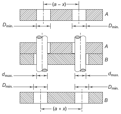
Figure 1 Assembly of Two Plates
Consider the worst geometric situation, when the following conditions exist:
(i) The holes are of the smallest size,Dmin,
(ii) The bolts are of the largest size, dmax,
(iii) The plate A has a minimum spacing (a – x),
and
(iv) The plate B has maximum spacing (a + x).
Considering the plate A, the center to center distance between bolts is given by
Eq. 1
(a - x ) + 2 ( Dmin / 2 ) - 2 ( dmax / 2 )
or
Eq. 2
(a – x) + ( Dmin– dmax )
Equating the expressions (a) and (b),
Eq. 3
x = ( Dmin– dmax )
The tolerance on center distance is given by
Eq. 4
( a ± x )
In case there are a number of holes, one hole is considered as the master or reference hole and the location of other holes should be provided with the required tolerance.
Reference:
Geometric Boundaries IV, The Interpretation and Application of ASME Y1.5-2018
Kelly Bramble, ASME Senior GDTP. FAA A&P
Related:
- Tolerance Calculator Floating Fastener Condition
- Tolerance Calculator Fixed Fastener Condition
- Tolerance Calculator Projected Tolerance Zone
- Tolerance Stackup Analysis
Link to this Webpage:
© Copyright 2000 -
2024, by Engineers Edge, LLC
www.engineersedge.com
All rights reserved
Disclaimer |
Feedback
Advertising
| Contact