Related Resources: calculators
C-Section No. 2 of 1b Loading Concentrated Intermediate Torque applied Deflection and Stress Equatio
C-Section with Concentrated Intermediate Torque applied Deflection and Stress Equations and Calculator #2 of 1b Loading .
Loading configuration left end free to twist and warp right end fixed (no twist or warp).
Formulas for the elastic deformations of uniform thin-walled open members under torsional loading.
Per. Roarks Formulas for Stress and Strain - Formulas for torsional properties and stresses in thin-walled open cross sections, Table 10.2.
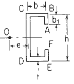
Section Dimensional Definitions
Figure 1
Loading Configuration (Section Shown May not Match Section given in Figure 1)
Loading configuration left end free to twist and warp right end fixed (notwist or warp)
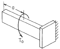
Figure 2
Loading Declarations Image (Section Shown May not Match Section given in Figure 1)
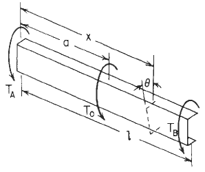
Concentrated intermediate torque of C-Section Beam Orientation Declarations Image
Figure 3
Preview: C-Section thin wall stress and torsional properties #2b calculator
C-Section Properties Constants Formulas See: Figure 1
![]()
![]()
Selected maximum values of stress and torsion
![]()
Stress throughout the thickness at corners A and D
|
Shear stress due to warping rigidity Throughout the thickness on the top and bottom flanges at |
|
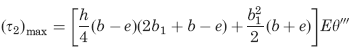
Shear stress due to torsional rigidity
![]()
Left end free to twist and warp right end fixed (no twist or warp)
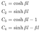
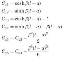
Boundary values for Loading condition See Figure 2
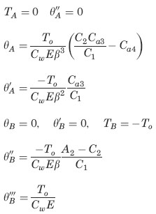
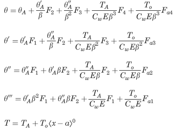
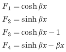
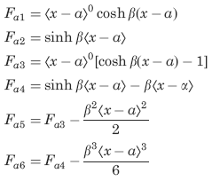
The following constants and functions are hereby defined in order to permit condensing the tabulated formulas which follow.
Concentrated intermediate torque See Figure 3
![]()
Where (when used in equations and this calculator):
Point 0 indicates the shear center se "Concentrated intermediate torque of Channel Beam Orientation Declarations image ";
e = distance from a reference to the shear center (in, m);
K = torsional stiffness constant (in4, m4);
C =warping constant (in6, m6);
τ1 = shear stress due to torsional rigidity of the cross section (lbsf/in2, m2);
τ2 = shear stress due to warping rigidity of the cross section (lbsf/in2, m2);
σx = bending stress due to warping rigidity of the cross section (lbsf/in2, m2);
E = modulus of elasticity (lbs/in2, m2);
G = modulus of rigidity (shear modulus) of the material (lbs/in2, m2);
To = applied torsional load (in-lbs, N-m);
to = applied distributed torsional load (lbsf/in, N/m);
TA and TB are the reaction end torques at the left and right ends, respectively (in-lbs, N-m);
θ = angle of rotation at a distance x from the left end (radians).
θ', θ'', θ''', = are the successive derivatives of y with respect to the distance x;
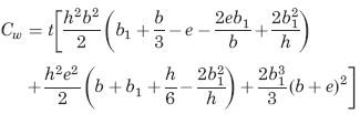
Cw = the warping constant for the cross section;
A, B, C, D, E, F, e, h, b1= Dimensional data Figure 1 (in, m).
All rotations, applied torsional loads, and reaction end torques are positive as shown (CCW when viewed from the right end of the member)
Unit step function defined by use of ⟨ ⟩
⟨ x - θ ⟩0
if x < a, ⟨ x - a ⟩n =0;
if x > a, ( x - a) n ;
The function sinh β
β = ( KG/CwE)1/2
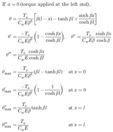
Supplemental selected special cases and maximum values (not included in calculator), See Figure 2.
Reference:
Roarks Formulas for Stress and Strain, 7th Edition, Table 10.2 and 10.3 Formulas for torsional properties and stresses in thin-walled open cross sections.
Link to this Webpage:
© Copyright 2000 -
2024, by Engineers Edge, LLC
www.engineersedge.com
All rights reserved
Disclaimer |
Feedback
Advertising
| Contact