Related Resources: calculators
Intermediate Arc-Flash Boundary Equations and Calculator for Arcing Current per IEEE 1584-2018
Electrical and Electronics Design and Engineering
Intermediate Arc-Flash Boundary Equations and Calculator for Arcing Current per IEEE 1584-2018
The arc flash boundary (AFB) is the minimum 'safe' distance from exposed energized conductors or circuit parts that has a potential for an arc fault.
Related:
Arc Flash Hazard Calculations Procedure and Considerations For Medium Voltage System
Preview: Intermediate Arc-Flash Boundary Equations and Calculator for Arcing Current
|
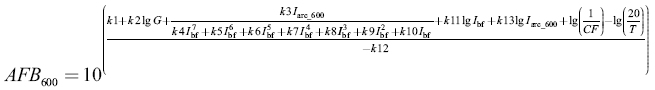
Equation 1
Open AFB600 Calculator (Pop-up Window) |
|
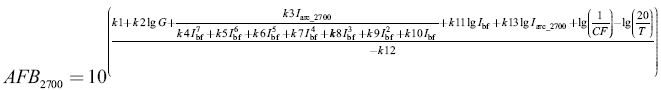
Equation 2
Open AFB2700 Calculator (Pop-up Window) |
Where:
AFB600 = arc-flash boundary for Voc = 600 V (mm)
AFB2700 = arc-flash boundary for Voc = 2700 V (mm)
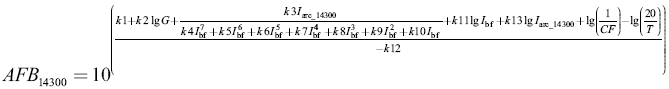
AFB14300 = arc-flash boundary for Voc = 14 300 V (mm)
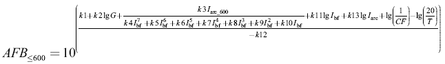
AFB≤600 = arc-flash boundary for Voc ≤ 600 V (mm)
G = gap between electrodes (mm)
Iarc_600 = rms arcing current for 600 V (kA)
Iarc_2700 = rms arcing current for 2700 V (kA)
Iarc_14300 = rms arcing current for 14300 V (kA)
Iarc = rms arcing current for Voc ≤ 600 V [obtained using "Final Arc Current Equations and Calculator"] (kA)
Ibf = bolted fault current for three-phase faults (symmetrical rms) (kA)
CF = correction factor for enclosure size (CF = 1 for VOA and HOA configurations)
T = arc duration (ms)
lg = log10
k1 to k13 from table given below
Table A Coefficients (AFB600 and AFB≤600 )
|
600 V
|
k1
|
k2
|
k3
|
k4
|
k5
|
k6
|
k7
|
k8
|
k9
|
k10
|
k11
|
k12
|
k13
|
|
VCB
|
0.753364
|
0.566
|
1.752636
|
0
|
0
|
-4.783E-09
|
0.000001962
|
-0.000229
|
0.003141
|
1.092
|
0
|
-1.598
|
0.957
|
|
VCBB
|
3.068459
|
0.26
|
-0.098107
|
0
|
0
|
-5.767E-09
|
0.000002524
|
-0.00034
|
0.01187
|
1.013
|
-0.06
|
-1.809
|
1.19
|
|
HCB
|
4.073745
|
0.344
|
-0.370259
|
0
|
0
|
-5.382E-09
|
0.000002316
|
-0.000302
|
0.0091
|
0.9725
|
0
|
-2.03
|
1.036
|
|
VOA
|
0.679294
|
0.746
|
1.222636
|
0
|
0
|
-4.783E-09
|
0.000001962
|
-0.000229
|
0.003141
|
1.092
|
0
|
-1.598
|
0.997
|
|
HOA
|
3.470417
|
0.465
|
-0.261863
|
0
|
0
|
-3.895E-09
|
0.000001641
|
-0.000197
|
0.002615
|
1.1
|
0
|
-1.99
|
1.04
|
Table B Coefficients AFB2700
|
2700 V
|
k1
|
k2
|
k3
|
k4
|
k5
|
k6
|
k7
|
k8
|
k9
|
k10
|
k11
|
k12
|
k13
|
|
VCB
|
2.40021
|
0.165
|
0.354202
|
-1.557E-12
|
4.556E-10
|
-4.186E-08
|
8.346E-07
|
5.482E-05
|
-0.003191
|
0.9729
|
0
|
-1.569
|
0.9778
|
|
VCBB
|
3.870592
|
0.185
|
-0.736618
|
0
|
-9.204E-11
|
2.901E-08
|
-3.262E-06
|
0.0001569
|
-0.004003
|
0.9825
|
0
|
-1.742
|
1.09
|
|
HCB
|
3.486391
|
0.177
|
-0.193101
|
0
|
0
|
4.859E-10
|
-1.814E-07
|
-9.128E-06
|
-0.0007
|
0.9881
|
0.027
|
-1.723
|
1.055
|
|
VOA
|
3.880724
|
0.105
|
-1.906033
|
-1.557E-12
|
4.556E-10
|
-4.186E-08
|
8.346E-07
|
5.482E-05
|
-0.003191
|
0.9729
|
0
|
-1.515
|
1.115
|
|
HOA
|
3.616266
|
0.149
|
-0.761561
|
0
|
0
|
7.859E-10
|
-1.914E-07
|
-9.128E-06
|
-0.0007
|
0.9981
|
0
|
-1.639
|
1.078
|
Table C Coefficients AFB14300
|
14300 V
|
k1
|
k2
|
k3
|
k4
|
k5
|
k6
|
k7
|
k8
|
k9
|
k10
|
k11
|
k12
|
k13
|
|
VCB
|
3.825917
|
0.11
|
-0.999749
|
-1.557E-12
|
4.556E-10
|
-4.186E-08
|
8.346E-07
|
5.482E-05
|
-0.003191
|
0.9729
|
0
|
-1.568
|
0.99
|
|
VCBB
|
3.644309
|
0.215
|
-0.585522
|
0
|
-9.204E-11
|
2.901E-08
|
-3.262E-06
|
0.0001569
|
-0.004003
|
0.9825
|
0
|
-1.677
|
1.06
|
|
HCB
|
3.044516
|
0.125
|
0.245106
|
0
|
-5.043E-11
|
2.233E-08
|
-3.046E-06
|
0.000116
|
-0.001145
|
0.9839
|
0
|
-1.655
|
1.084
|
|
VOA
|
3.405454
|
0.12
|
-0.93245
|
-1.557E-12
|
4.556E-10
|
-4.186E-08
|
8.346E-07
|
5.482E-05
|
-0.003191
|
0.9729
|
0
|
-1.534
|
0.979
|
|
HOA
|
2.04049
|
0.177
|
1.005092
|
0
|
0
|
7.859E-10
|
-1.914E-07
|
-9.128E-06
|
-0.0007
|
0.9981
|
-0.05
|
-1.633
|
1.151
|
VCB: Vertical conductors/electrodes inside a metal box/enclosure
VCBB: Vertical conductors/electrodes terminated in an insulating barrier inside a metal box/enclosure
HCB: Horizontal conductors/electrodes inside a metal box/enclosure
VOA: Vertical conductors/electrodes in open air
HOA: Horizontal conductors/electrodes in open air
Reference:
IEEE 1584-2018
Verify results and send feedback if a discrepancy is found.
Link to this Webpage:
© Copyright 2000 -
2024, by Engineers Edge, LLC
www.engineersedge.com
All rights reserved
Disclaimer |
Feedback
Advertising
| Contact