Related Resources: calculators
L Pipe Bend Guided Cantilever Beam Equation and Calculator
Fluids Engineering and Design
Beam Stress and Deflection Calculators
L Pipe Bend Guided Cantilever Beam Equation and Calculator
Detailed stress analysis requires involved mathematical analysis and is generally performed by computer programs. However, such involved analysis is not typically required for many piping systems because the piping arrangements and temperature ranges at which they operate are usually simple to analyze.
The guided cantilever beam method of evaluating L bends can be used to design L bends, Z bends, pipe loops, branch take-off connections, and some more complicated piping configurations. The guided cantilever equation [see Equation (3)] is generally conservative because it assumes that the pipe arrangement does not rotate. The anchor force results will be higher because of the lack of rotation, and rigorous analysis is recommended for complicated or expensive systems.
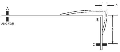
Figure 1 Guided Cantilever Beam
Preview: L Pipe Bend Guided Cantilever Beam Calculator
Equation (1) may be used to calculate the length of leg BC needed to accommodate thermal expansion or contraction of leg AB for a guided cantilever beam (Figure 1).
Equation 1
L = [ ( 3 · Δ · D · E ) / ( ( 144 in2 / ft2) · SA ) ]1/2
Where:
L = length of leg BC required to accommodate thermal expansion of
long leg AB, ft
Δ = thermal expansion or contraction of leg AB, in.
D = actual pipe outside diameter, in.
E = modulus of elasticity, psi
SA = allowable stress range, psi
The guided cantilever method of designing L bends assumes no restraints; therefore, care must be taken in supporting the pipe. For horizontal L bends, it is usually necessary to place a support near point B (see Figure 1), and any supports between points A and C must provide minimal resistance to piping movement; this is done by using slide plates or hanger rods of ample length, with hanger components selected to allow for swing no greater than 4°. For L bends containing both vertical and horizontal legs, any supports on the horizontal leg must be spring hangers designed to support the full weight of pipe at normal operating temperature with a maximum load variation of 25%.
The force developed in an L bend that must be sustained by anchors or connected equipment is determined by the following equation:
Equation 2
F = ( 12 · Ec · I · Δ ) / ( ( 1728 in3 / ft3 ) · L3 )
Where:
F = force, lb
Ec = modulus of elasticity, psi
I = area moment of inertia, in4
L = length of offset leg, ft
Δ = deflection of offset leg, in.
1728 in3 / ft3 = ft3 to in3 conversion
Related:
- Thermal Expansion of Metal Pipe
- Pipe Support Hanger Spacing and Pipe Wall Thickness
- Steel Threaded Rods Capacities ASTM A36 used for Pipe Support Hangers
- Fastener, Bolt and Screw Design Torque and Force Calculation
- Bolt Torque, Axial Clamp Force, Bolt Diameter Calculator
- Torque vs Tension Bolts Table Chart SAE J429 Bolts
- Torque Values Stainless Steel Bolt Table Chart | Engineering Reference and Online Tools
References
- ASHRAE Handbook of Fundamentals, 2021 Inch-Pound Edition
Link to this Webpage:
© Copyright 2000 -
2024, by Engineers Edge, LLC
www.engineersedge.com
All rights reserved
Disclaimer |
Feedback
Advertising
| Contact