Cylinder Interference Press Fit Equations and Calculator
Engineering Calculators
Torque Engineering and Design
Strength of Materials
Open Radial displacements due to Poisson effect, thermal expansion and rotation Design Calculator
Requires a Java Enabled Browser
Alternatively:
- Diameter Change for Cylinder Press and Shrink Fits Analysis Equations and Calculator
- Interference Fit Force Required the Press Together Hub and Shaft Equations and Calculator
Radial displacements due to Poisson effect, thermal expansion and rotation
An interference fit, also known as a press fit or friction fit, is a fastening between two parts which is achieved by friction after the parts are pushed together, rather than by any other means of fastening.
An interference fit is generally achieved by shaping the two mating parts so that one or the other, or both, slightly deviate in size from the nominal dimension. The word interference refers to the fact that one part slightly interferes with the space that the other is taking up.
Industry standard interference fits have been established by ASME/ANSI B4.1-1967 revised 2009. It is recommended that for typical end engineering design applications this standard be used.
- Locational interference fits, LN are used where accuracy of location is of prime importance, and for parts requiring rigidity and alignment with no special requirements for bore pressure. Such fits are not intended for parts designed to transmit frictional loads from one part to another by virtue of the tightness of fit. These conditions are covered by force fits.
- Force or shrink fits FN) constitute a special type of interference fit, normally characterized by maintenance of constant bore pressures throughout the range of sizes. The interference, therefore, varies almost directly with diameter, and the difference between its minimum and maximum value is small to maintain the resulting pressures within reasonable limits.
For example, a shaft may be ground slightly oversize and the hole in the bearing (through which it is going to pass with an interference fit) may be ground slightly undersized. When the shaft is pressed into the bearing, the two parts interfere with each other's occupation of space. The result is that both parts elastically deform slightly to fit together creating an extremely high force which results in extremely high friction between the parts — so high that even large amounts of torque cannot turn one of them relative to the other; they are locked together and turn in unison.
Open Radial displacements due to Poisson effect, thermal expansion and rotation Design Calculator
Requires a Java Enabled Browser
Radial displacements due to Poisson effect, thermal expansion and rotation
(1) Inner Body Poisson Radial Displacement (click on formula to enlarge)

(2) Thermal Radial Mismatch (click on formula to enlarge)

(3) Outer Body Radial Displacement Caused by Rotation (click on formula to enlarge)

(4) Inner Body Radial Displacement Caused by Rotation (click on formula to enlarge)

(5) Interface Pressure as a result of Diametrical Interference (click on formula to enlarge)
For the Outer Body Subjected to Internal Pressure, Axial Force, Torque, and Rotation.
(6) Radial Displacement of the inner Surface Caused by Internal Pressure.
(7) Radial Stress Caused by internal Pressure
(8) Circumferential Stress Caused by Axial Force
(9) Axial Stress Caused by Torque
![]()
(10) Shear Stress Caused by Torque
(11) Circumferential Centrifugal Stress at the Inner Surface

(12) Von Mises Stress at the Inner Surface (click on formula to enlarge)

For the Inner Body Subjected to External Pressure , Axial Force, Torque and Rotation
(13) The Radial Displacement Caused by External Pressure
(14) Radial Stress Caused by External Pressure
(15) Circumferential Stress Caused by External Pressure
(16) Axial Stress Caused by Axial Force
![]()
(17) Shear Stress Caused by Axial Force
![]()
(18) Circumferential Centrifugal Stress at the outer Surface (click on formula to enlarge)

(19) Von Mises Stress at the outer Surface (click on formula to enlarge)

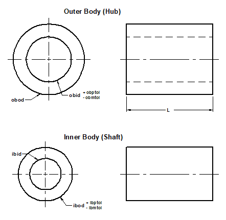
Figure 1 Dimensional Specification Hub and Shaft (click on image to enlarge)
(20) Ideal case interference fit
diametrical Interference = obid - ibod
where
obid = outer body inside diameter nominal
ibod = inner body outside diameter nominal
(21) Worst case minimum interference fit
diametrical Interference min. = (obid + obptol) - (idob - ibmtol)
where
obptol = outer body inner diameter plus tolerance
ibmtol = inner body minus tolerance
obid = outer body inside diameter (Nominal)
ibod = inner body outside diameter (Nominal)
(22) Worst case maximum interference fit
diametrical Interference max. = (obid - obmtol) - (ibod + ibptol)
Where:
obmtol = outer body inner diameter minus tolerance
ibptol = inner body plus tolerance
obid = outer body inside diameter (Nominal)
ibod = inner body outside diameter (Nominal)
Open Press Fit Design Calculator
Requires a Java Enabled Browser
Webpage / Equations Contribution:
Alexander Slocum, MIT Department of Mechanical Engineering
References: Slocum, A.H.Precision Machine Design, 1995, Society of Manufacturing Engineers, Dearborn Published by Prentice Hall, 1992.inee
Related Resources:
- Plastic (Polymer) Post and Hub Press Fit Equation and Calculator
- Interference Pressure Mechanical Tolerances Variability Equations and Calculator
- Class V Locational Interference Tolerance Chart for Holes and Bolts
- Bushing and Plain Bearings Press or Shrink Fit Design and Application
- Preferred Force Shrink Fits Chart ANSI B4.1 Calculator
Link to this Webpage:
© Copyright 2000 -
2024, by Engineers Edge, LLC
www.engineersedge.com
All rights reserved
Disclaimer |
Feedback
Advertising
| Contact