Related Resources: calculators
Maximum Reinforcement Steel Area per. ACI 318 Calculator
Civil Engineering and Design
Strength of Materials Basics and Equations | Mechanics of Materials
Maximum Reinforcement Steel Area per. ACI 318 Equations and Calculator
In a ductile failure mode, the steel yields in tension before the concrete crushes in compression. (The opposite would be a brittle failure mode.) The area of tension steel for which steel yielding occurs simultaneously with concrete crushing in compression is known as the balanced steel area, Asb. An under-reinforced beam is defined as one having a steel area less than Asb. An over-reinforced beam has more steel than Asb.
The balanced steel area is
Eq. 1
Asb = ρsb · b · d = 0.85 · f 'c · Acb / fy = 0.85 · f 'c · ab · b / fy
Asb = 0.85 · f 'c · β1 cb b / fy
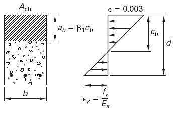
Figure 1 illustrates that the compression area for balanced conditions, Acb, extends from the most compressed fiber to a depth equal to ab.
Eq. 2(a), SI
ab = β1 ( 600 / ( 600 + fy ) ) d
Eq. 2(b), US
ab = β1 ( 87,000 / ( 87,000 + fy ) ) d
Figure 1, Beam at Balanced Condition
The factor β1 is defined as
Eq. 3(a), SI
β1 = 0.85 [ f 'c ≤ 27.6 MPa]
Eq. 3(b), US
β1 = 0.85 [ f 'c ≤ 4,000 lbf/in2]
Eq. 3(c), SI
β1 = 0.85 - 0.05 (( f 'c - 27.6 ) / 6.9 ) ≥ 0.65 MPa
Eq. 3(d), US
β1 = 0.85 - 0.05 (( f 'c - 4,000 ) / 1,000) ≥ 0.65 lbf/in2
Combining Eq. 1 and Eq. 2 with Acb = abb, for rectangular sections, the balanced steel area is
Eq. 4(a), SI
Asb = ρsb · b · d = ( ( 0.85 ·β1 · f 'c ) / fy · (600 / ( 600 + fy ) ) · b · d
Eq. 4(b), US
Asb = ρsb · b · d = ( ( 0.85 · β1 · f 'c ) / fy · (87,000 / ( 87,000 + fy ) ) · b · d
Previous versions of ACI 318 ensured the steel would fail in tension before the concrete failed in compression (i.e., ductile failure) by limiting the maximum reinforcement to 75% of the balanced reinforcement. (This provision is still present in ACI 318 Sec. B10.3.3 of the alternative provisions.)
Eq. 5
As,max = 0.75 · Asb [alternative provisions only]
For unified design, the ductile failure is ensured by specifying a minimum tensile steel strain, εt,min of 0.004.
The unified design provisions limit the maximum reinforcement in a flexural member (with factored axial load less than 0.1f'cAg) to that which would result in a net tensile strain, εt , not less than 0.004 [ACI 318 Sec. 10.3.5]. The fraction of the balanced reinforcement ratio equivalent to a steel strain of 0.004 depends on both the concrete ultimate compressive strength and the steel tensile yield strength. For a singly reinforced section with grade 60 reinforcement, this is equivalent to a maximum reinforcement ratio of 0.714ρb. (By comparison, the ACI 318 App. B limit of ρmax = 0.75ρb results in a net tensile strain of 0.00376.) At the net tensile strain limit of 0.004, the strength reduction factor of ACI 318 Sec. 9.3.2, Φ, is reduced to 0.817.
It is almost always advantageous to limit the net tensile strain in flexural members to a minimum of 0.005, which is equivalent to a maximum reinforcement ratio of 0.63ρb [ACI 318 Sec. R9.3.2.2], even though the code permits higher amounts of reinforcement that produce lower net tensile strains. Where member size is limited and extra strength is needed, it is best to use compression reinforcement to limit the net tensile strain so that the section is tension controlled.
Where:
Asb = Area, in2 (mm2)
ab = depth from equation 2, in (mm)
b = width, in (mm)
cb = distance, in (mm)
d = Beam effective depth (tension to steel centroid), in, (m)
β1 = stress constant, equation 3, lbf/in2 (MPa)
fy = Tension steel yield strength, lbf/in2 (MPa)
f 'c = Compressive strength of concrete, lbf/in2 (MPa)
bw = Width of web, ft, (m)
ρsb = reinforment steel ratio
Reference
- ACI 318 Building Code Requirements for Structural Steel, paragraph 10.5 Minimum reinforcement of flexural members
- Civil Engineering Reference Manual, Fifteenth Edition, Chapter 48, p. 50.6, Paragraph 8 (Maximum Steel Area), Michael R. Lindeburg, PE
Related
- Minimum Reinforcement Steel Area Calculator
- Rebar Two Parallel Legs One Angled Leg Center Line Length Equation and Calculator
- Standard ReBar Shapes Formula and Calculator
- Concrete Splitting Tensile Strength Test Equations and Calculator
- Tensile Thread Stress Area Equation and Calculator - 180 ksi and More
- Material Tensile Shear and Yield Strength of Engineering Materials Table
- Concrete Modulus of Elasticity Equations and Calculator
- Modulus of Elasticity, Youngs Modulus Table and Calculator
- Bulk Modulus for Materials Metals and Liquids
- Circular Formed Rebar Center Line Length Equation and Calculator
- Young's Modulus (Elastic Modulus ) Equation
- Ultimate Strength, Modulus of Elasticity , Yield Point of Metals Table Chart
- Concrete Foundation Anchor Bolts Design
- Manual of Concrete Design ACI
- Reinforced Concrete Beam Design to BS8110 Calculator
- Reinforced Concrete Beam Design per. ACI 318-08 Calculator Spreadsheet
- Concrete Pad Foundation Design Spreadsheet Calculator
- Concrete Structural Designers Guide
Link to this Webpage:
© Copyright 2000 -
2024, by Engineers Edge, LLC
www.engineersedge.com
All rights reserved
Disclaimer |
Feedback
Advertising
| Contact