Related Resources: calculators
Spline Transmitted Torque and Pressure Analysis Formula and Calculator
Gear Design and Engineering Data
Spline Transmitted Torque and Pressure Analysis Formula and Calculator
Splines are keys which are made integral with the shaft. They are used when there is a relative axial motion between the shaft and the hub. The gear shifting mechanism in automobile gearboxes requires such type of construction. Splines are cut on the shaft by milling and on the hub by broaching. A splined connection, with straight splines, is shown in Fig. 1.0. The following notations are used:
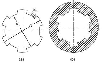
Figure 1 Splines: (a) Shaft (b) Hub
Preview Spline Transmitted Torque and Pressure Calculator
D = major diameter of splines (mm)
d = minor diameter of splines (mm)
l = length of hub (mm)
n = number of splines
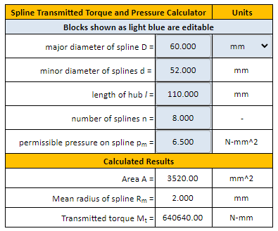
The torque transmitting capacity of splines is given by,
Eq. 1.0
Mt = pm · A · Rm
Where:
Mt = transmitted torque (N-mm)
pm = permissible pressure on spline (N/mm2)
A = total area of splines (mm2)
Rm = mean radius of splines (mm)
The area A is given by,
Eq. 2.0,
A = .5 ( D - d ) · l · n
Eq. 3.0,
Rm = ( D + d ) / 4
Substituting the above values in Eq. (1.0),
Eq. 4.0
Mt = ( 1 / 8 ) · pm · l · n · ( D2 - d2 )
Manipulated for Length of Hub
Eq. 5.0
l = ( 8 · Mt ) / [ pm · n · ( D2 - d2 ) ]
Reference:
Design of Machine Elements, Third Edition
V. B Bhandari
Professor and Head Department of Mechanical
Engineering
Vishwakarma Institute of Technology,
Pune, India
Related:
- Involute Spline ANSI B92.1 Equations and Design
- Spline Socket Go and No Go Gages
- Spline Engineering Design Formula
- Hexagon and Spline Sockets for Metric Socket Head Cap Screws
- Key and Spline Drive Bit Tools per. ASME B18.3
- Involute Spline and Serration Universal Design Calculator
- Shaft with Two Splines Deflection, Stress Equation and Calculator
- Shaft with One Spline Deflection, Stress Equation and Calculator
Link to this Webpage:
© Copyright 2000 -
2024, by Engineers Edge, LLC
www.engineersedge.com
All rights reserved
Disclaimer |
Feedback
Advertising
| Contact