In piping and flow systems, when fluid move through pipe fittings such as elbows, tees, U-joints, manifolds, and sudden expansions the fluid becomes turbulent, causing noise, vibration, cavitation, separation, and accelerated and reverse flows. If these pipe fittings are used next to pumps, flow meters, compressors, control valves, and process equipment, the equipment will experience failures and unscheduled downtimes, lost or reduced production, excessive repair costs, loss of flow, head and efficiency, safety concerns, environmental spills, and the need for more installation space.
The CRV® eliminates elbow induced turbulence which negatively impacts the performance of pumps, compressors, control valves, flow meters, and other equipment. The CRV® inputs to the flow a counteracting gyroscopic motion to the resultant elbow induced gyroscopic motion, and enables the fluid to negotiate the turn through the elbow and then exit the elbow with a flat velocity profile. This results in an even distribution of process fluid through any cross-section of the elbow and transforms the elbow into the equivalent of a straight length of pipe, and there is no additional pressure drop with the use of a CRV®.
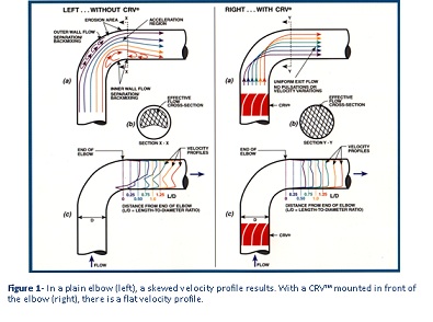
Flow through a plain elbow is illustrated in the Figure 1 (a-left). As a result of the forces acting on the fluid as it passes through the elbow, two flow separation regions result where a void or vapor space is created. Because of the existence of these flow separation regions, the remaining pipe cross-sectional area through which the fluid must pass is significantly reduced, as shown in Figure 1 (b-left), and the local velocity is increased and directed towards the outer wall of the elbow. This high velocity region is one of the reasons why elbows exhibit high-pressure drop as compared to a straight pipe.
Measured velocity profiles of the fluid downstream of a plain elbow at six locations are shown in Figure 1(c-left). As expected for a plain elbow, Figure 1 (c-left) shows that there is a high velocity region in the straight section of pipe along the outside of the elbow, and a low velocity/backflow region in the straight section of pipe along the inside of the elbow.
When the CRV® is placed immediately upstream of an elbow, it rotates the flow entering the elbow. As a consequence, the fluid negotiates the turn with all the streamlines traveling approximately the same distance (equal flow path lengths) from entrance to exit, as illustrated in Figure 1(a-right), and the flow separation regions are eliminated. The entire pipe cross-sectional area is available for fluid flow as shown in Figure 1(b-right). For this reason, the total drop in pressure in a CRV®�plus-elbow-combination is 25% to 50% less than that of a plain elbow without a CRV®. In Figure 1(c-right), the measured velocity profile with a CRV® becomes relatively flat at the elbow exit and almost perfectly flat at a downstream position of L/D=1.25.
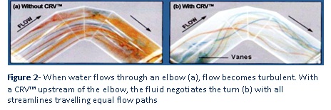
Flow separation and the rotational effect of the CRV® are also shown in Figures 2(a) and 2(b) where the use of different colored dyes trace the flow streamlines in a transparent 6-inch diameter short radius elbow carting water. In Figure 2(a), the dyes follow the elbow streamlines and the inner and outer flow separation regions can be seen along with exit turbulence. In Figure 2(b) where the dyes are injected at the end of the CRV® (beginning of the elbow), the dye streamlines rotate 180-degrees, as does the fluid itself, producing equal fluid flow path lengths around the elbow exit. The blade angle of a CRV® is uniquely designed to match each elbow geometry and flow path length.
Using computational fluid dynamics modeling, one can reproduce, in Figure 3, the laboratory-measured velocity profiles of Figure 1(c). The plain elbow velocity profile is shown in Figure 3(a)-left and illustrates the high velocity along the outer wall of the elbow and the low/backflow velocity along the inner wall of the elbow. Figure 3(b)-left shows the velocity profile of the cross -sectional area at the end of the simulation. Figure 3(a)-right and 3(b)-right show the same simulation with a CRV® directly in the front of the elbow. Note the dramatic flattening of the velocity profile and the resultant elimination of flow separation/backflow regions.