Related Resources: gears
Basic Rack Tooth Gear Profiles DIN 867
Basic Rack Tooth Gear Profiles DIN 867
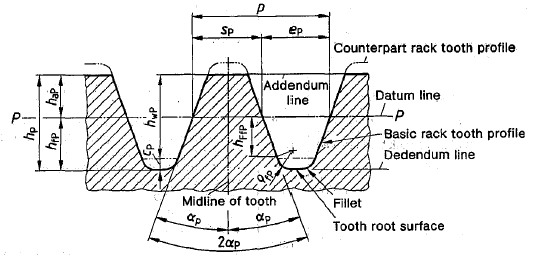
Figure 1
The following defines the basic rack tooth profile for gears specified under DIN 53, 867 and similar.
Datum Line (PP), Addendum Lime, Dedendum Line
The datum line is that straight line on which the tooth thickness is equal to the space width or half the pitch:
sp = ep = p/2
Basic Rack Tooth Profile of Mating Gear
The basic rack tooth profile of the mating gear (counterpart rack tooth profile) is equal to the cylindrical gear basic rack tooth profile folded through 180° around the datum line.
Module, Pitch
The module, m is a length which determines the size of the basic rack tooth profile and thus of the associated cylindrical gear teeth.
Ap = pi m
Pressure Angle
Pressure angle:  is formed by the straight flanks an a line perpendicular to the datum line. The flanks of a tooth are symmetrical about the midline of the tooth.
is equal to 20° for a basic rack tooth profile as specified in this standard.
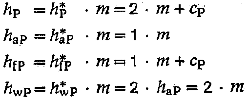
Tooth Depth, addendum, dedendum, bottom clearance, common tooth depth
Tooth depth, hp of the basic rack tooth profile is subdivided by the datum line into the addendum, hap and dedendum hfp.
The bottom clearance, cp is the difference between the dedendum of the basic rack tooth profile and the addendum of the counterpart rack tooth profile.
Common tooth depth, hwp of the rack and counterpart rack tooth profiles is the total of the two tip depths
Bottom Clearance Coefficient
Generally, the bottom clearance, cp is equal to cp x m = 1,1 x m to 0,4 x m This depends on the requirements of the gear design and application.
Fillet Radius
Fillet radius, Qfp starts at or below tooth depth and can be defined as:
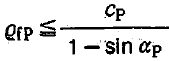
Formula 7
The fillet radius should not exceed the calculated value obtained when the left and right flank of a space on a basic rack tooth profile merge with a fillet without forming a tooth root surface. With Hfp as specified, Qfp is to be calculated from the following equation:
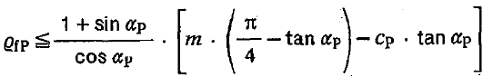
Formula 8
Apply the following to basic rack tooth profiles as specified in this document (with =20° and hfp = 1 x m + cp). Formula 7 must be used for cp not exceeding 0,295 x m and formula 8 for cp exceeding 0,295. The notation associated with formulae 7 and 8 are given in Figure 2. Only one pair of values, cp = 0,25 m and Qfp = 0,38m has been specified in ISO 53.
Note: Fillet radius of the cylindrical gear basic rack tooth profile determines the tip rounding radius of the fillet produced on the basic rack tooth profile. The radii od curvature of the fillet produced on the cylindrical gear shall be equal to or greater than the tip rounding radius of the tool according to the numbers of teeth and profile displacements of the generating gear.
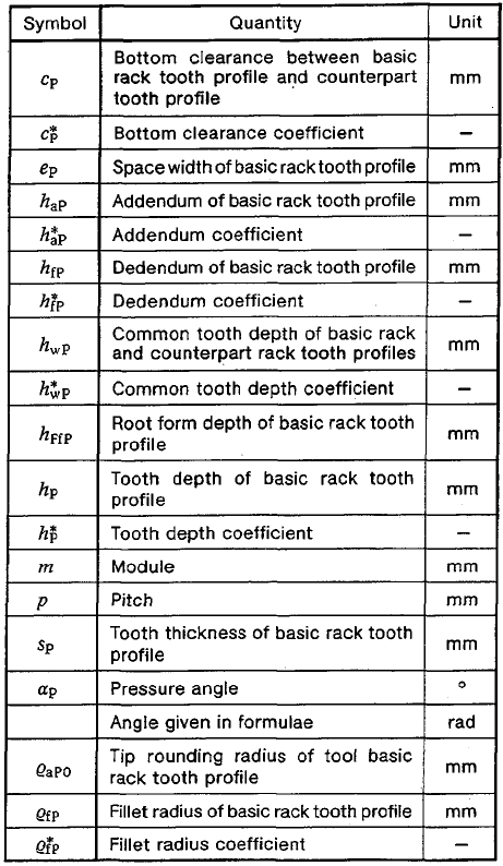

Figure 2
Relationships between bottom clearance coefficient and fillet radius coefficient according to formulae 7 & 8 for = 20° and hfp = 1m +cp.
The part of the diagram shaded area gray shows the area including possible pairs of values for e the cases in which the tooth flanks merge with the fillet.
Usable Flanks, Root Form Depth
Straight pairs of the tooth flanks form usable flanks. Where the flanks merge with the surface, the root form depth of the basic rack tooth profile is defined by:

Link to this Webpage:
© Copyright 2000 -
2024, by Engineers Edge, LLC
www.engineersedge.com
All rights reserved
Disclaimer |
Feedback
Advertising
| Contact