Related Resources: hardware
Thrust Load Capacity Retaining Rings
ANSI Hardware Design Guide and Charts
Thrust Load Capacity of Retaining Rings
Thrust Load Capacity: The thrust load capacities shown in the table below include safety factors. Usually, a safety factor of 2 is used for groove thrust load calculations when the load is applied through a retained part and groove with both having sharp corners and where the minimum side clearance exists between the retained part and the shaft or bore.
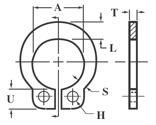
Dimensions of Inch Series Self-Locking External Retaining Rings
A safety factor of 3 is usual for calculations of thrust load capacity based on ring shear.
|
Shaft Diameter |
Ring |
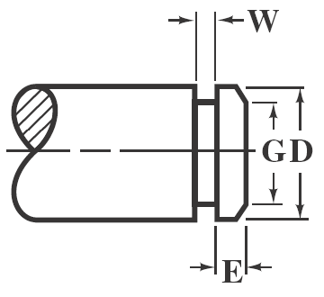
Optical Groove |
1Static Thrust Load (lb) |
|||||
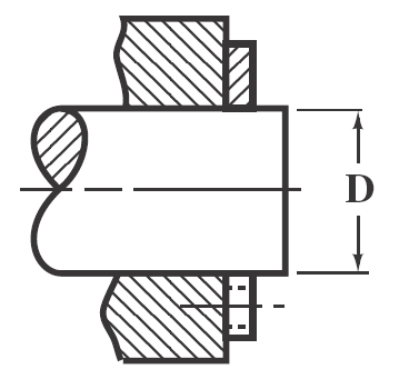
Min. D |
Max. D |
Free Dia. A |
Thickness T |
Diameter G |
Width W |
Margin E |
Ring |
Groove |
0.078 |
0.080 |
0.074 |
0.025 |
The use of grooves with these shaft sizes is not suggested. |
10 |
0 |
||
|
0.092 |
0.096 |
0.089 |
0.025 |
10 |
0 |
|||
|
0.123 |
0.127 |
0.120 |
0.025 |
20 |
0 |
|||
0.134 |
0.138 |
0.130 |
0.025 |
20 |
0 |
|||
0.154 |
0.158 |
0.150 |
0.025 |
22 |
0 |
|||
0.185 |
0.189 |
0.181 |
0.035 |
25 |
0 |
|||
0.248 |
0.252 |
0.238 |
0.035 |
0.240 |
0.041 |
0.030 |
35 |
90 |
0.310 |
0.316 |
0.298 |
0.042 |
0.303 |
0.048 |
0.030 |
50 |
110 |
0.373 |
0.379 |
0.354 |
0.042 |
0.361 |
0.048 |
0.030 |
55 |
185 |
|
0.434 |
0.440 |
0.412 |
0.050 |
0.419 |
0.056 |
0.030 |
60 |
280 |
|
0.497 |
0.503 |
0.470 |
0.050 |
0.478 |
0.056 |
0.040 |
65 |
390 |
0.622 |
0.628 |
0.593 |
0.062 |
0.599 |
0.069 |
0.045 |
85 |
570 |
0.745 |
0.755 |
0.706 |
0.062 |
0.718 |
0.069 |
0.050 |
90 |
845 |
1 Thrust Load Safety Factors: Ring, 1; groove, 2.
Source: Industrial Retaining Rings, 7100 Series. All dimensions are in inches. Depth of groove d = (D − G)/2. Standard material: carbon spring steel (SAE 1060-1090). Thickness indicated is for unplated rings; for plated, phosphate coated, and stainless steel rings, the maximum ring thickness may be exceeded by 0.002 inch.
Related:
- Retaining Snap Ring Stress and Failure Formulas and Calculator
- Internal Retaining Snap Ring Sizes and Groove Design Chart
- Internal Retaining Snap Ring Sizes and Groove Design sizes 1.562 to 3.000
- Centrifugal Capacity Retaining Snap Rings
- Metric Tapered Retaining Snap Rings Size Chart
Link to this Webpage:
© Copyright 2000 -
2024, by Engineers Edge, LLC
www.engineersedge.com
All rights reserved
Disclaimer |
Feedback
Advertising
| Contact