Related Resources: manufacturing
Extrusions General Shape Mechanical Tolerances
Mechanical Tolerances
Design for Manufacturability and Assembly DFM DFMA Premium Resources
Extrusions General Shape Mechanical Tolerances
A direct extrusion is made in the previously described manner. The maximum circumscribing circle for aluminum, magnesium, copper, and copper alloys is approximately 305 mm (12 in.), but some of the new presses have increased the maximum circle to 685 mm (27 in.). The maximum circumscribing circle for alloy steel and stainless steel is 136.5 mm (5.375 in.), and for carbon and titanium, 165.1 mm (6.5 in.).
Extruded shapes can be straightened in lengths up to 18.29 m (60 ft). Maximum product weight per 0.305 m (1 ft) of extruded shape is 9.07 kg (20 lb) for aluminum and 6.8 kg (15 lb) for steel. The minimum cross section is not less than 65 mm2 (0.10 in.2) for aluminum and not less than 323 mm2 (0.50 in.2) for steel. Tables 4-44 and 4-45 provide tolerance information for extrusion processes.
Coextrusion: coextrusion results when two different alloys are extruded together to form a composite part as in Fig. 1.
Alclad tubing is an example of coextrusion. In this instance, a clad layer of one aluminum alloy can be placed inside, outside, or on both sides of a core alloy of another composition.
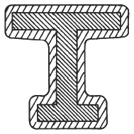
Figure 1 - Coextrusion
Cold Extrusion There are two methods of cold extrusion: impact extrusion and the Hooker process. Aluminum, tin, copper alloys, and steel are worked by these two extrusion methods. The low strength, ductile alloys are easier to extrude by the Hooker processor by impact extrusion. When higher mechanical properties are required in the final product, heat treatable grades are used. However, extrusions from these grades are more susceptible to defects, such as laps or cracks, than those extruded from the lower strength alloys. A description of the processes follows:
1. Impact extrusion. There are three variants of the impact extrusion process:
a. Forward, or direct, wherein the metal flows in the same direction as the applied force
b. Backward, or indirect, wherein the metal flow is opposite to the force, or back over the punch
c. Opposed, wherein the metal is forced to flow simultaneously with, and opposite to, the direction of applied force.
Table 1 - General Shape Tolerances of Extrusions
| Type of Tolerance |
Dimensions Which Tolerance Applies |
Tolerance ± |
| Straightness | Circumscribing circle diameter up through 38.07 mm (1.499 in. ) | 1.27 mm (0.05 in. per ft for minimum thickness up through 2.39 mm (0.094 in.)); 0.318 mm (0.0125in.) per ft for minimum thickness 2,41 mm (0.095 in.) and up |
| 38.1 mm (1.5 in.) and up | 0.318 mm (0.0125 in. ) per ft | |
| Twist | Circumscribing circle diameter up through 38.07 mm (1.499 in.) | 0.0174 rad per 304.8 mm (1 deg per ft) |
| 38.1 to 75.94 mm (1.50 to 2.99 in. ) | 0.0087 rad per 304.8 mm; 0.0872 rad total (0.5 deg per ft); (5 deg total) | |
| 76.2 mm (3.0 in.) and up | 0,0044 rad per 304.8 mm; 0.0524 rad total (0.25 deg per ft); (3 deg total) | |
| Contour | Deviation from specified | 0.13 mm per 25.4 mm (0.005 in. per in. of chord width (0.13 mm (0.005 in. ) minimum) |
| Corner and fillet radii | Sharp corners Radius up through 5.004 mm (0.197 in.) | 0.396 mm (0.0156 in.) 0.792 mm (0.0312 in.) |
| Specified radius 4.775 mm (0.188 in.) and up | 10% | |
| Angles | Minimum leg thickness; under 4.775 mm (0.188 in.) | 0.0349 rad (2 deg) |
| 4.775 mm to 190.5 mm (0.188 to 0.750 in.) | 0.262 rad (1.5 deg) | |
| 19.05 mm (0.75 in. ) to solid | 0.0174 rad (1 deg) | |
| Flatness | 0.101 mm (0.004 in.) per 25.4 mm (1 in.) of width 0.10 mm (0.004 in.) minimum | |
| Surface roughness | Section thickness: up through 1.60 mm (0.063 in.) | Maximum depth of defect: 0.038 mm (0.0015 in.) |
| 1.63 to 3.18 mm (0.064 to 0.125 in.) | 0.051 mm (0.002 in.) | |
| 3.20 to 4.78 mm (0.126 to 0.188 in.) | 0.064 mm (0.0025 in.) | |
| 4.80 to 6.35 mm (0.189 to 0.250 in.) | 0.076 mm (0.003 in. ) | |
| 6.38 mm (0.251 in.) and up | 0.102 mm (0.004 in. ) |
Table 2 Mechanical Tolerances for Impact Extrusions
| Diameter | Outside |
Diameter |
Tolerances Inside |
± Diameter |
Bottom |
Thickness |
| mm (in.) | mm |
(in.) |
mm |
(in.) |
mm |
(in.) |
| <19.0 (<0.75) | 0.03 |
(0.001) |
0.05 |
(0.002) |
0.18 |
(0.007) |
| >19.0 to 38.1 (> 0.75 to 1.5) | 0.08 |
(0.003) |
0.10 |
(0.004) |
0.25 |
(0.01) |
| >38.1 to 44.4 (> 1.5 to 1.75) | 0.13 |
(0.005) |
0.15 |
(0.006) |
0.30 |
(0.012) |
| >44.4 to 50.8 (> 1.75 to 2) | 0.15 |
(0.006) |
0.18 |
(0.007) |
0.30 |
(0.012) |
| >50.8 to 63.5 (> 2 to 2.5) | 0.18 |
(0.007) |
0.20 |
(0.008) |
0.30 |
(0.012) |
| >63.5 to 88.9 (> 2.5 to 3.5) | 0.23 |
(0.009) |
0.25 |
(0.01) |
0.38 |
(0.015) |
| >88.9 to 101.6 (> 3.5 to 4) | 0.25 |
(0.01) |
0.28 |
(0.011) |
0.38 |
(0.015) |
| >101.6 to 114.3(> 4 to 4.5) | 0.28 |
(0.011) |
0.30 |
(0.012) |
0.38 |
(0.015) |
| >114.3 to 127.0(> 4.5 to 5) | 0.36 |
(0.014) |
0.38 |
(0.015) |
0.38 |
(0.015) |
| >127.0 to 152.4(> 5 to 6) | 0.51 |
(0.02) |
0.51 |
(0.02) |
0.38 |
(0.015) |
Source
- MIL-HDBK-727 Design Guidance for Producibility
Related
- Design for Extrusion Considerations, Tolerances and Review
- Aluminum Extrusion Dimensions and Tolerances Specification
- Plastic Extrusion Design Manufacturing Review
- Feature Based Cost Estimation Extruded Parts
- Handbook of Manufacturing Processes
- Design for Producibility
Link to this Webpage:
© Copyright 2000 -
2024, by Engineers Edge, LLC
www.engineersedge.com
All rights reserved
Disclaimer |
Feedback
Advertising
| Contact