Related Resources: materials
Rectangular Section Bar Steel Springs
Springs Made From Rectangular Section Bar Steel Design and Calculations
Lays down calculations for design of helical compression springs made from rectangular or square section wire or bar.
Applies to springs of special designs where it becomes imperative to use them fue to space limitations. Springs made from rectangular section bar should be avoided as far as possible as the springs made from circular section bar can be stressed to the same values for a ower weight of material used and for shorter overall length.
The design of such springs is based final rectangular section. Suitable trapezoidal section may have to be selected to arrive at final rectangular section.
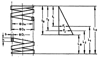
b = Side of cross-section perpendicular to axis of the spring, mm
f1, f2 = Sp.ring deflections corresponding to axial loads F2, f2, mm
fB = Lo - LB - Spring deflection in mm, related to axial load FB, mm
h = Side of cross-section parallel to axis of the spring, mm
if = Number of working coils
iG = Total number of coils
w = Dm/b = Coil ratio (w > 4)
Do = External coil diameter, mm
Di = Internal coil diameter, mm
Dm = Mean coil diameter, mm
F1, F2, etc = Axial load, related to load lengths, L1, L2, etc, N
FB = Axial load related to length of compressed spring Ls, N
G -Modulus of rigidity, N/mm?
L0 = Length of unloaded spring, mm
L1, L2 = Load lengths of spring, mm
LB = Length of compressed spring (all coils closed ), mm
Rs = Shear stress under load F, N/mm2
RsB = Shear stress under load FB, N/mm2
Sc = ( Δ F / Δ f ) Spring rate, N/mm2
ε = Elasticity ( resilience) coefficient, dependent on ratio of cross-section on side lengths b/h or h/b.
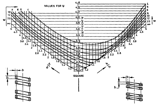
ψ = Stress coefficient, dependent on ratio of cross-section side lengths b/h or h/b and on coil ratio w.
Type of Coiling:
Coiled on Edge -In this case longer side of the cross-section is perpendicular to the axis of the spring. This type of coiling enables large deflections, short block lengths and a high ratio of internal to external coil diameters.
Flat Coiled -In this case the longer side of the cross-section is parallel to the axis of the spHng. This type of coiling enables large free lengths and low ratios of external to internal diameters.
Loading -Spring made from rectangular section bars are usually used to obtain the maximum load capacity for a given space. Consequently such springs are often highly stressed. Long service cannot be expected under such conditions, especially if the range of stress is high as well as the stress at maximum load.
Flat Spring Design Formula
Shear Stress, Rs
![]()
Spring Deflection, f
![]()
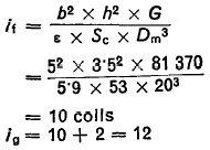
Number of Turns
![]()
![]()
Values of Ψ and ε are given in figure below.
Values for ε
|
b/h or h/b
|
1
|
1·1
|
1·2
|
1·3
|
1·4
|
1·5
|
1·6
|
1·7
|
1·8
|
1·9
|
2
|
-
|
|
ε
|
5·59
|
5·61
|
5·67
|
5·77
|
5·88
|
6·02
|
6·17
|
6·33
|
6·50
|
6·68
|
6·87
|
-
|
|
b/h or h/b
|
2·2
|
2·4
|
2·6
|
2·8
|
3
|
3·2
|
3·4
|
3·6
|
3·8
|
4
|
4·5
|
5
|
|
ε
|
7·26
|
7·67
|
8·09
|
8·51
|
8·95
|
9·39
|
9·83
|
10·28
|
10·73
|
11·19
|
12·33
|
13·48
|
Examples of design of compression springs made from square and rectangular section material are as follows:
Example A
A-1.
Design of cold coiled compression spring made from square section material, subjected to a static or infrequently varying load.
A compression spring is required to meet a load F1 = 250 N at L1 = 50 mm and F2 = 400 N at f2 = 40 mm. b = 30 mm.
The space available permits a maximum outside coil diameter Do = Dm + b = 30 mm.
A-1.1
Spring rate Sc from F1, F2 and L1, L2 is obtained as under:
( F2 - F1 ) / ( L1 - L2 ) = 150 N / 10 mm = 15 M/mm
Moreover, from load/deflection line we can obtain the free length as under:
f1 = F1( f2 - f1 ) / ( f1 - f2 ) = 150 N x 10/50 = 16.66 mm
The free length of the spring is therefore Lo = 50 + 16.66 mm = 66.66 mm
A-1.2
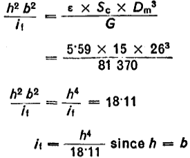
Assuming a mean Ø Dm = 26 mm, so that the side length of the section is restricted to b - h < 4.0 mm.
From equation (Number of working coils):
![]()
Thus:
A-1.3
Assuming a minimum space S, between individual coils as 0·1 x h since the specified length l2 = 40 mm, we have the following:
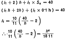
The result of the graphic solution is
b = h - 3·5
it = 7·3
ig = 7·3 + 2 = 9·3 and LB = 32·55 mm
Coil ratio W = 26 / 3·4 = 7·65
A-l.4 Checking the maximum shear stress from formula
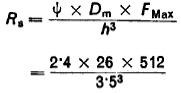
= 745 M/mm2
The above stress is safe and plain carbon spring steel wire can be chosen for the manufacture of the springs.
Example B
Design of a cold coiled helical spring made from rectangular section wire subjected to a static or infrequently varying load.
B-l.
A compression spring is required to meet a load F1 = 530 N at L1 -55 mm and F2 = 1 060 N at Ls = 45 mm. The space available permits a maximum outside dia Do =I Dm + of 25·5 mm and a rod of 14 mm should pass freely inside the spring in fitment.
B-l.1
Spring rate Sc from F1 , F2 and L1 , L2 is obtained as under:
( F2 - F1 ) / ( L1 - L2 ) = 530 N / 10 mm = 53 M/mm
From load/deflection line we can obtain the free length as under:.
f1 = F1( f2 - f1 ) / ( f1 - f2 ) = 150 N x 10/50 = 16.66 mm
= 530 x 10 / 530 = 10 mm
The free length of the spring is therefore
Lo -55 + 10 = 65 mm
B-1.2
Assuming a mean dia of Dm = 20 and b -5 and h = 3·5 we shall calculate the number of coils from formula
Solid height LB = 12 x 3.5 = 42.0 mm
Assuming minimum space S, between individual coils as 0.1 X h, the required total clearance is 0.1 x 3·5 x 10 = 3.5 mm whereas clearance available between L2 and LB is only 3 mm. Hence try alternative thickness of wire.
Choose a thickness say 3.45 mm and recalculate the number of coils
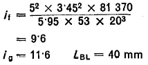
8-l .3
Check for maximum shear stress RsB from formula
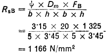
In view of the above high stress, material chosen should be alloyed spring steel wire such as chrome silicon or chrome vanadium spring steel wire.
Shot Peening of Springs -Springs made from rectangular section bars may be shot peened to increase their life. Lower stress range shall be used for the purposes of calculations even when the springs are shot peened.
Reference:
ISO 7906, Part IV Helical Comression Springs Design Standard
Link to this Webpage:
© Copyright 2000 -
2024, by Engineers Edge, LLC
www.engineersedge.com
All rights reserved
Disclaimer |
Feedback
Advertising
| Contact