Related Resources: mechanical-tolerances
Drill and Counterbore Sizes for Socket Head Cap Screws per. ASME B18.3
Drill and Counterbore Sizes for Socket Head Cap Screws per. ASME B18.3
Dimension units in inches.
Related:
|
Nom.
Size Screw |
Nom.
Size Screw Decimal |
Nominal Drill Size
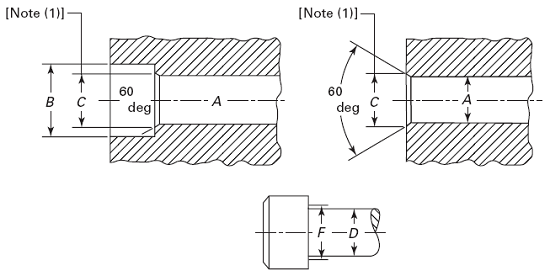
A |
Counterboore
Diameter B |
Countersink
C Note 1 |
|||
|
Close Fit
Note 2 |
Normal
Fit Note 3 |
||||||
|
No. or
Fractional Size |
Decimal
|
No. or
Fractional Size |
Decimal
|
||||
|
0
|
0.0600
|
51
|
0.067
|
49
|
0.073
|
1/8
|
0.074
|
|
1
|
0.0730
|
46
|
0.081
|
43
|
0.089
|
5/32
|
0.087
|
|
2
|
0.0860
|
3/32
|
0.094
|
36
|
0.106
|
3/16
|
0.102
|
|
3
|
0.0990
|
36
|
0.106
|
31
|
0.120
|
7/32
|
0.115
|
|
4
|
0.1120
|
1/8
|
0.125
|
29
|
0.136
|
7/32
|
0.130
|
|
5
|
0.1250
|
9,64
|
0.141
|
23
|
0.154
|
1/4
|
0.145
|
|
6
|
0.1380
|
23
|
0.154
|
18
|
0.170
|
9/32
|
0.158
|
|
8
|
0.1640
|
15
|
0.180
|
10
|
0.194
|
5/16
|
0.188
|
|
10
|
0.1900
|
5
|
0.206
|
2
|
0.221
|
3/8
|
0.218
|
|
1/4
|
0.2500
|
17/64
|
0.266
|
9/32
|
0.281
|
7/16
|
0.278
|
|
5/16
|
0.3125
|
21/64
|
0.328
|
11/32
|
0.344
|
17/32
|
0.346
|
|
3/8
|
0.3750
|
25/64
|
0.391
|
13/32
|
0.406
|
5/8
|
0.415
|
|
7/16
|
0.4375
|
29/64
|
0.453
|
15/32
|
0.469
|
23/32
|
0.483
|
|
1/2
|
0.5000
|
33/64
|
0.516
|
17/32
|
0.531
|
13/16
|
0.552
|
|
5/8
|
0.6250
|
41/64
|
0.641
|
21/32
|
0.656
|
1
|
0.689
|
|
3/4
|
0.7500
|
49/64
|
0.766
|
25/32
|
0.781
|
1-3/16
|
0.828
|
|
7/8
|
0.8750
|
57/64
|
0.891
|
29/32
|
0.906
|
1-3/8
|
0.963
|
|
1
|
1.0000
|
1-1/64
|
1.016
|
1-1/32
|
1.031
|
1-5/8
|
1.100
|
|
1-1/4
|
1.2500
|
1-9/32
|
1.281
|
1-5/16
|
1.312
|
2
|
1.370
|
|
1-1/2
|
1.5000
|
1-17/32
|
1.531
|
1-9/16
|
1.562
|
2-3/8
|
1.640
|
|
1-3/4
|
1.7500
|
1-25/32
|
1.781
|
1-13/16
|
1.812
|
2-3/4
|
1.910
|
|
2
|
2.0000
|
2-1/32
|
2.031
|
2-1/16
|
2.062
|
3-1/8
|
2.180
|
1. Countersink. It is considered good practice to countersink or break the edges of holes that are smaller than F (max.) in parts having a hardness which approaches, equals, or exceeds the screw hardness. If such holes are not countersunk, the heads of screws may not seat properly or the sharp edges on holes may deform the fillets on screws thereby making them susceptible to fatigue in applications involving dynamic loading. The countersink or corner relief, however, should not be larger than is necessary to insure that the fillet on the screw is cleared. Normally, the diameter of countersink does not have to exceed F (max.). Countersinks or corner reliefs in excess of this diameter reduce the effective bearing area and introduce the possibility of imbedment where the parts to be fastened are softer than the screws or brinnelling or flaring of the heads of the screws where the parts to be fastened are harder than the screws.
2. Close Fit. The close fit is normally limited to holes for those lengths of screws that are threaded to the head in assemblies where only one screw is to be used or where two or more screws are to be used and the mating holes are to be produced either at assembly or by matched and coordinated tooling.
3. Normal Fit. The normal fit is intended for screws of relatively long length or for assemblies involving two or more screws where the mating holes are to be produced by conventional tolerancing methods. It provides for the maximum allowable eccentricity of the longest standard screws and for certain variations in the parts to be fastened, such as: deviations in hole straightness, angularity between the axis of the tapped hole and that of the hole for the shank, differences in center distances of the mating holes, etc.
Link to this Webpage:
© Copyright 2000 -
2024, by Engineers Edge, LLC
www.engineersedge.com
All rights reserved
Disclaimer |
Feedback
Advertising
| Contact