Related Resources: mechanical-tolerances
Machined Tool Relief Grooves Dimensions and Tolerances
Geometric and Mechanical Tolerances Tables and Calculators
Design for Manufacturing and Assembly
Machining Tool Relief Grooves Dimensions and Tolerances
Size, Dimensions and Tolerances for Machined Tool Relief Grooves.
Per industry standards DIN ISO 509 and IS 3428
Relief Groove Definition: Clearance groove of specified form and dimensions created by removing material at an inner corner of a rotationally symmetric work piece and which is necessary for subsequent machining and assembly with mating parts.
Relief Groove Type E
Type E (see Figure 1 and Table 1) relief grooves are suitable where the planar surface is not subjected to high fatigue loads and where the cylindrical surface will be subsequently machined, if necessary. They are also suitable where mating parts have a relatively large counterbore or will not be in contact with the planar surface.
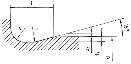
Figure 1 Relief Groove Type E
Where:
d1 = workpiece diameter
t1 = depth of cut
f = breadth of relief groove
z1 = machining allowance
r = radius of relief groove
A relief groove Type F (see Figure 2 and Table 1) is applied for work pieces, whose surfaces which are at right angle to one another are machined further, if necessary.
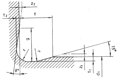
Figure 1 Relief Groove Type F
Where:
d1 = diameter of the work piece
t1, t2 = depth of cut
f, g = breadth of the relief groove
z1, z2 = machining allowance
r = radius of the relief groove
The relief groove of Type G (see Figure 3 and Table 1) is applied for work pieces with less load, for which as far as possible a smaller transition of the surfaces which are at right angles to one another, is required.

Figure 3 Relief Groove
d1 = diameter of the work piece
t1, t2 = depth of cut
f, g = breadth of the relief groove
z11, z2 = machining allowance
r = radius of the relief groove
A relief groove of Type H (see Figure 4 and Table 1) is applied for work pieces whose surfaces which are at right angles to one another are machined further, if necessary.
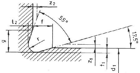
Figure H
d1 = diameter of the work piece
t1, t2 = depth of cut
f, g = breadth of the relief groove
z1, z2 = machining allowance
r = radius of the relief groove
Dimensions for Machined Relief Grooves, All Dimensions given in Millimeters Table 1
All dimensions in millimeters (mm)
(Premium Membership Required)
1 Relief grooves with radii of the series 1 are preferable.
2 The allocation to diameter range is not applicable for short offsets and thin walled parts. For manufacturing reasons, it would be sensible to effect several relief grooves on a single work piece with different diameters, in the same shape and size.
3 Type G only for work pieces with less load .
Machining Allowance
The machining allowance z1 and z2 given in Table 2 displaces the blend of the relief grooves into the machined surfaces by the amount e and e1,2 respectively as given in Fig. 5. This amount depends on the magnitude of z1 and z2 and the relevant entry1and runout angles of the relief grooves.
Figure 5 Machining Allowance
All Dimensions in millimeter (mm)
(Premium Membership Required)

e1, e2 = breadth of the machining transition
z1, z2 = machining allowance
Allocation of Dimensions of Relief Groove and Machining Allowance, Table 2
All Dimensions in millimeters
(Premium Membership Required)
Link to this Webpage:
© Copyright 2000 -
2024, by Engineers Edge, LLC
www.engineersedge.com
All rights reserved
Disclaimer |
Feedback
Advertising
| Contact