Related Resources: mechanical-tolerances
Shaft to Shaft Axial Alignment Tolerances
Mechanical Design and Engineering Tolerances and Variability
Shaft to Shaft Axial Alignment Tolerances
Design for shaft-to-shaft alignment is the positioning of the rotational centers of two or more shafts so that the shafts are co-axial when the machine is in operation. The purpose of shaft alignment is to increase the operating life span of rotating machinery and to achieve high efficiency. It may not easy to detect misalignment when machines are running, but secondary effects of misalignment can be observed, such as excessive radial and axial vibration; high temperature in casings, bearings, or lubricant; loose, broken or missing coupling bolts or foundation bolts; cracks in shafts; and excessive amounts of lubricant leakage.
There are no industry standard specifications for shaft alignment, however, there are defined limits for shaft-to-shaft alignment of coupled machines. The limits are defined in terms of two measures of misalignment, angularity and axial offset.
Shaft Angular Misalignment. Angular misalignment is the difference in the slope of one shaft, as compared to slope of the other shaft. The units are expressed as rise/run. Rise is measured in mils (1 mil = 0.001 inch), and the run (distance along shaft) is measured in inches. The process of correcting this type of alignment problem is sometimes called gap or face alignment.
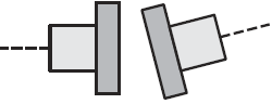
Angular Misalignment of Shafts
Axial Offset Misalignment. Axial offset misalignment is the distance between the shaft centers of rotation measured at the plane of power transmission or coupling center.
There are four alignment parameters to be measured and corrected; vertical angularity, vertical offset, horizontal angularity, and horizontal offset. Values in the tables (in & mm vs rpm) below may be used as a general guide for acceptable limits of misalignment. Proper shaft alignment is especially critical when shafts are running at high speeds, thus the allowable limits of misalignment decrease as shaft speeds increase.
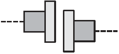
Axial Misalignment of Shafts
Shaft - to -Shaft Misalignment RPM vs Tolerances in and mm units Tables
Premium Membership Required
When the machines to be permanently mounted and the other one to be movable. The fixed unit is usually the driven machinery, such as the pump in a pump-motor pair. The second machine (usually the motor) is moved into approximate alignment (by eye and straight edge, for example) in preparation for measurements that will determine the magnitude and direction of moves required to put it in final alignment with the fixed machine. It is the movable machine whose shaft will be aligned with the shaft of the fixed machinery. The position of the movable machine is adjusted vertically by adding and/or removing shims from under its feet, and horizontally by making small lateral moves as required until satisfactory final alignment is obtained.
References:
Dubbel Handbook of Mechanical Engineering, German Version, 1993
Engineering Design for Manufacturing and Assembly, 2016 Kelly L. Bramble
Link to this Webpage:
© Copyright 2000 -
2024, by Engineers Edge, LLC
www.engineersedge.com
All rights reserved
Disclaimer |
Feedback
Advertising
| Contact