Related Resources: mechanics machines
Solid Disk Flywheel Design
Engineering Analysis
Gear Engineering and Design
Machine Design, Equation and Calculators
Solid Disk Flywheel Moment of Inertia and Shaft Stresses
The simple type of flywheel is a solid circular disk as shown in Fig. 1. The mass moment of inertia of this disk is given by,
 eq. 1a
where,
I = mass moment of inertia of disk (kg-m2)
m = mass of disk (kg)
R = outer radius of disk (m)
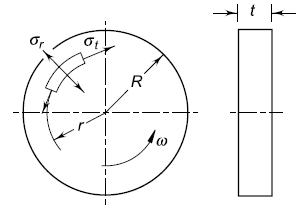
Fig. 1, Solid Disk Flywheel
The mass of the disk is given by
m = πR2tρ (b) eq. 1b
where,
t = thickness of disk (m)
r = mass density of fl ywheel material (kg/m3)
From (a) and (b),
![]() eq. 3
eq. 3
There are two principal stresses in the rotating disk—the tangential stress σt, and radial stress σr. The general equations for these stresses at a radius r are as follows:
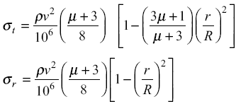 eq. 4
eq. 4
where,
σt = tangential stress at radius r (N/mm2)
σr = radial stress at radius r (N/mm2)
µ = Poisson’s ratio (0.3 for steel and 0.27 for cast iron)
v = peripheral velocity (m/s) (Rω)
The maximum tangential stress and maximum radial stress are equal and both occur at (r = 0).
Therefore,
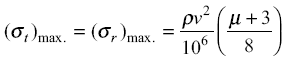 eq. 5
eq. 5
Example:
A machine is driven by a motor, which exerts a constant torque. The resisting torque of the machine increases uniformly from 500 N-m to 1500 N-m through a 360° rotation of the driving shaft and drops suddenly to 500 N-m again at the beginning of the next revolution. The mean angular velocity of the machine is 30 rad/s and the coeffi cient of speed fl uctuations is 0.2. A solid circular steel disk, 25 mm thick, is used as flywheel. The mass density of steel is 7800 kg/m3 while Poisson’s ratio is 0.3. Calculate the outer radius of the fl ywheel disk and the maximum stresses induced in it.
Solution:
Given:
ω = 30 rad/s
Cs = 0.2
t = 25 mm
µ = 0.3
ρ = 7800 kg/m3
Step I
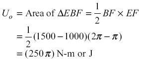
Energy output from flywheel (Uo)
The turning moment diagram is shown in Fig. 2 The mean torque Tm supplied by the motor is given by,
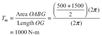
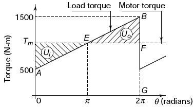
Figure 2, Turning Moment Diagram
The maximum and minimum angular velocities occur at points E and B respectively. Therefore,
Step II Outer radius of flywheel From Eq. 21.4,
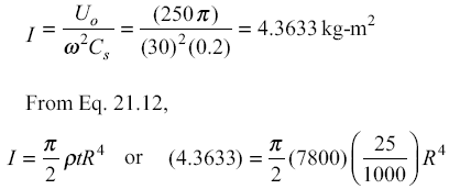
![]()
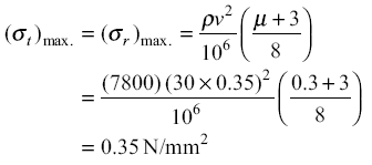
Step III Stresses in flywheel
The tangential and radial stresses are maximum at the centre of the disk. From Eq. 21.13,
References: S Timoshenko—Strength of Materials—Part II, MacMillan and Co. Ltd.
Link to this Webpage:
© Copyright 2000 -
2024, by Engineers Edge, LLC
www.engineersedge.com
All rights reserved
Disclaimer |
Feedback
Advertising
| Contact