Related Resources: motors
Metric Stepper Motors Dimensions Table
Power Transmission
Electric Motors and Driver Review
Stepper Control Motors Size and Dimensions Table for metric mounting flanges. NEMA Mounting Flanges for NEMA Frames 55 to 1080.
Note: This document annotates dimensional data specified by NEMA standard (see bottom of webpage). Many industry stepping motor manufacturers have chosen to deviate from this industry standard.
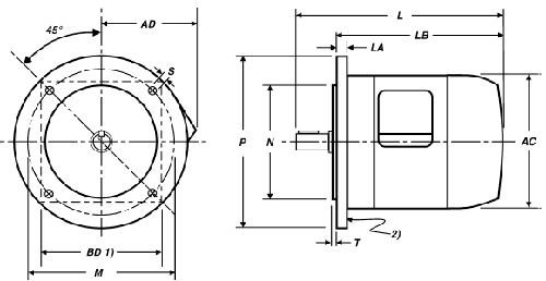
Dimensions for mounting flanges for metric dimension motors
ICS 16-2001 Page 52
|
Flange
Number M |
BDa
(square flange) maximum |
N
|
P
Maximum |
Number
of holes |
S
Free holes (for FF flange) |
Tapped
Holes (for FT flange) thread |
T
Maximum mm |
||||
|
Nominal
mm |
Tolerance
|
Nominal
mm |
Tolerance
|
||||||||
|
µm
|
µm
|
µm
|
µm
|
||||||||
|
55
|
53
|
40
|
+0
|
-16
|
70
|
4
|
5.8
|
+300
|
0
|
M5
|
2.5
|
|
65
|
60
|
50
|
+0
|
-16
|
80
|
4
|
5.8
|
+300
|
0
|
M5
|
2.5
|
|
70
|
60
|
50
|
+0
|
-16
|
80
|
4
|
5.5
|
+300
|
0
|
M5
|
2.5
|
|
75
|
70
|
60
|
+0
|
-25
|
90
|
4
|
5.8
|
+300
|
0
|
M5
|
2.5
|
|
85
|
80
|
70
|
+0
|
-25
|
105
|
4
|
7
|
+360
|
0
|
M6
|
2.5
|
|
100
|
90
|
80
|
+0
|
-30
|
120
|
4
|
7
|
+360
|
0
|
M6
|
3
|
|
115
|
105
|
95
|
+0
|
-35
|
140
|
4
|
10
|
+360
|
0
|
M8
|
3
|
|
130
|
120
|
110
|
+0
|
-35
|
160
|
4
|
10
|
+360
|
0
|
M8
|
3.5
|
|
145
|
130
|
110
|
+0
|
-35
|
165
|
4
|
9
|
+360
|
0
|
M8
|
3
|
|
165
|
140
|
130
|
+0
|
-35
|
200
|
4
|
12
|
+430
|
0
|
M10
|
3.5
|
|
200
|
174
|
114.3
|
+0
|
-25
|
225
|
4
|
13.5
|
+430
|
0
|
M12
|
4
|
|
215
|
190
|
180
|
+0
|
-35
|
250
|
4
|
14.5
|
+430
|
0
|
M12
|
4
|
|
265
|
225
|
230
|
+0
|
-40
|
300
|
4
|
14.5
|
+430
|
0
|
M12
|
4
|
|
300
|
265
|
250
|
+0
|
-45
|
350
|
4
|
18.5
|
+520
|
0
|
M16
|
5
|
|
350
|
300
|
300
|
+0
|
-52
|
400
|
4
|
18.5
|
+520
|
0
|
M16
|
5
|
|
400
|
340
|
350
|
+0
|
-57
|
450
|
8
|
18.5
|
+520
|
0
|
M16
|
5
|
|
500
|
415
|
450
|
+0
|
-57
|
550
|
8
|
18.5
|
+520
|
0
|
M16
|
5
|
|
600
|
495
|
550
|
+0
|
-57
|
660
|
8
|
24
|
+520
|
0
|
M20
|
6
|
|
740
|
600
|
680
|
+0
|
-57
|
800
|
8
|
24
|
+520
|
0
|
M20
|
6
|
|
940
|
750
|
880
|
+0
|
-57
|
1000
|
8
|
28
|
+520
|
0
|
M24
|
6
|
|
1080
|
865
|
1000
|
+0
|
-57
|
1150
|
8
|
28
|
+520
|
0
|
M24
|
6
|
a BD dimensions shown (for non-circular flanges) are approximate values for reference only. An actual BD value is determined by themanufacturer. For square flanges, the BD value chose n by the manufacturer may require rounding of the square flange corners to fitwithin the P maximum diameter values shown.
Reference: NEMA ICS 16 Standard
Link to this Webpage:
© Copyright 2000 -
2024, by Engineers Edge, LLC
www.engineersedge.com
All rights reserved
Disclaimer |
Feedback
Advertising
| Contact