Related Resources: pressure-vessel
Piping Drums Headers ASME Pressure Vessel Code Equations and Calculators
ASME Pressure Vessel Design and Engineering
ASME SECTION I – Piping, Drums, and Headers Pressure and Wall Thickness Equations and Calculator:
The following formulae are found in ASME Section I, paragraph PG-27.2.2. The information for piping, drums, or headers may be given with either the inside I or outside D measurements.
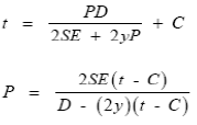
Pressure and Wall Thickness Equations and Calculator Preview
Using the inside radius:
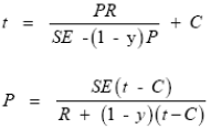
Pressure and Wall Thickness Equations and Calculator Preview #2
Where:
t = Minimum Design Wall Thickness (in);
P = Design Pressure (psi);
D = Tube Outside Diameter (in);
R = Tube Radius (in);
E = Tube Welding Factor (1.0 for seamless pipe; 0.85 = for welded pipe);
y = Wall Thickness Welding Factor (0.4 for 900°F & lower; 0.7 for 950°F & up);
C = Corrosion Allowance (0 for no corrosion; 0.0625 in. commonly used; 0.125 in. maximum);
S = Maximum Allowable Stress According to ASME Section II.
Example - Steam Piping:
Calculate the required minimum thickness of a seamless steam piping at a pressure of 900 psi gauge and a temperature of 700°F. The piping is 10.77 in O.D., (10 inches nominal) plain end; the material is
SA-335 – P1, alloy steel. Allow a manufacturer’s tolerance allowance of 12.5%.
Note: Before starting calculations check the material stress table in ASME Section II, Table 1A:
SA-335 – P1 = 13,800 psi – allowable stress – Div.1. Use equation:
P = [900 psi]
D = [10.77 in]
C = 0
S = [13,800] – (SA-335 – P1 alloy steel at 700°F)
E = 1.0
y = 0.4 (Ferritic steel less than 900°F)
![]()
Link to this Webpage:
© Copyright 2000 -
2024, by Engineers Edge, LLC
www.engineersedge.com
All rights reserved
Disclaimer |
Feedback
Advertising
| Contact