Related Resources: thermodynamics
Closed System Cycles Ideal & Real Diesel Cycle Class 9
Thermodynamics Data, Equations, Charts, Equations and Calculators
Closed System Cycles – Compression-Ignition Engines – Ideal & Real Diesel Cycle Class 9
Objective(s):
At the completion of the lecture, students should:
1) Understand the working principle of a real internal combustion engine (ICE) operating via compressionignition (CI).
2) Recognize the approximate P-V cycle of a real CI-ICE engine.
3) Apply thermodynamic processes to approximate the CI-ICE cycle as the Ideal Diesel cycle.
4) Identify the importance of the design parameters “Compression ratio” and “Cutoff ratio” and apply them to the Diesel cycle.
5) Be able to calculate the maximum theoretical efficiency of the Ideal Diesel Cycle and compare to the Otto Cycle.
6) Understand engine design constraints due to ambient conditions, fuel properties, and engine integrity.
7) Understand using general polytropic processes for the compression and expansion strokes to simulate heat transfer during cold early-startup times and later hot-engine times.
Methodology:
Lecture with animations and video (1, 2, The Story of Rudolf Diesel) shown via projector. In-class CI-ICE demo unit.
Terminology:
Compression-ignition (CI): When fresh air is adiabatically compressed above the autoignition temperature of the fuel. Near the point of maximum compression, highly atomized fuel is injected at high pressure into the cylinder and the fuel spontaneously combusts in the hot environment, converting chemical potential energy into mechanical energy as the expanding combustion gases push the piston downward.
Only one stroke of a 4-stroke cycle produces power. The rest of the strokes consume energy via sliding-surface friction and/or gas compression.
When conducting dimensional analysis, revolutions per minute are typically important. It should be noted there are two revolutions in every full cycle of a 4-stroke ICE. If an engine operates at 2,400 RPM, then there are (2,400 rev/min)(1/2 cycles/rev) = 1,200 cycles/min = 20 cycles/s = 20 Hz.
2-Stroke SI-ICEs complete the same series of operations, only the strokes are combined. The individual strokes are not as distinctly defined for 2-stroke engines as they are for 4-stroke engines:
1) Intake-and-ignition stroke.
2) Compression-and-exhaust stroke.
2-stroke engines have one power stroke in every two-stroke cycle, making them more powerful on a per-cycle basis. They can be made lighter than 4-stroke engines, but due to design, have historically caused more pollution due to some unburnt fuel escaping during the “scavenging” process that occurs between the exhaust and compression strokes. There is one full cycle for every revolution, so at 2,400 RPM, there are 2,400 cycles/min = 40 cycles/s = 40 Hz.
Design variables:
The CI-ICEs we’re analyzing are of the piston-in-cylinder type. We need to know the dimensions of the cylinder to figure out the maximum and minimum volume.
Bore: the diameter of the piston within the cylinder.
Stroke: the maximum distance traveled by the piston (i.e. distance between top and bottom dead center).
Clearance volume: the minimum achievable volume of the cylinder; occurs at when piston is Top Dead Center.
Displacement volume: the volume swept out by the piston during a full stroke.
Compression ratio: the ratio between the maximum and minimum achievable volumes.
Cutoff ratio: The ratio between the intermediate volume at the end of the isobaric process when heat stops being added and the volume at top-dead-center.
Fuel: It’s said diesel engines can burn almost any liquid fuel, whereas gasoline engines have much more stringent standards. That’s largely true. Diesels can combust very “dirty” fuels, such as marine heavy fuel, which is a dark, tarry or solid substance at room temperature. Many diesel engines to dely on the fuel’s lubricity to manage operating temperatures, so if the fuel is too thin or combusts too rapidly, it won’t work well in a diesel. New “dual fuel” engines employ natural gas as their fuel, with a small amount of diesel fuel serving as the igniter.
Speed control: It’s harder to stop a running diesel engine than a SI engine. To stop an SI engine, power to the spark plug is cut and the engine stalls quickly. The main method of controlling diesel engine speed is through fuel metering. More fuel → more power and speed. As long as the engine receives fuel, it will continue to run. So a fuel governor controls the amount of fuel, or cuts off the fuel supply completely. Runaway can occur when the ambient atmosphere contains sufficient quantities of flammable vapors to power the engine, even if the dedicated fuel supply is cut. This effect is depicted in the movie Deepwater Horizon.
What does the actual CI-ICE cycle look like on a P-V diagram?
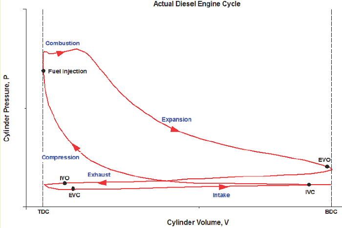
Figure 1: Credit "Engine Know How" Ideal Cycle:
We will analyze the CI-ICE using the Ideal Diesel Cycle as our thermodynamic basis for processes:
1) Intake (State 6 to State 1): The volume inside a cylinder isobarically increases from the minimum volume to the maximum volume. The work out of this process will be exactly canceled by the work consumed by the exhaust process. Air is introduced at its ambient properties if the engine is naturally aspirated. If the air is charged, then it will be at a higher pressure and (probably) temperature.
2) Compression (State 1 to State 2): The piston rises, adiabatically compressing the air from its largest volume to its smallest volume. This process requires an input of work. The autoignition temperature of the fuel must be achieved at some point during this process.
3) Active power (State 2 to State 3): At its maximum pressure, the gas is isobarically heated to its maximum temperature, which will be a design constraint. The total combustion occurs over some amount of time, which is exhibited by an isobaric change in volume.
4) Passive power (State 3 to State 4): The gas adiabatically expands from the point at which heat addition stops, back to the volume corresponding to BDC.
5) Cooling (State 4 to State 5): The gas isochorically cools back to the temperature it was at state 1. These two, (1) and (5), are actually identical states.
6) Exhaust (State 5 to State 6): The gas is isobarically compressed to its smallest volume and the total cycle is completed.
We typically won’t consider the Intake and Exhaust processes in our analyses, since they don’t actually contribute any net heat or work interactions in the overall cycle. We’ll instead focus on the progression from 1 to 2 to 3 to 4 back to 1 (which is identical to 5).
What does the ideal Diesel cycle look like on a P-V diagram?


The area bound between the compression & power strokes is the net useful work coming from the cycle:


The diesel cycle is theoretically less efficient than the otto cycle, but actual diesel engines are typically more efficient than actual gasoline engines because the compression ratio can be made much higher. However, if a diesel engine and gasoline engine both operate with the exact same compression ratio, the gasoline engine will be more efficient (at least based on ideal theory).
Based on an engineering analysis of the world’s largest diesel engine, the P-V plot appears a little skinnier than the generic plots shown above:

Modifications:
We assumed the compression and expansion (power) processes were perfectly adiabatic and frictionless to simplify the analysis. In actuality they aren’t, and the calculated thermal efficiency represents a theoretical best case scenario.
The “movement processes” (i.e. compression and power/expansion) may be modeled as polytropic processes, instead of adiabatic:
When the engine is cold, the compression process will have a smaller exponent associated with volume, representing a process somewhere between isothermal and adiabatic. The passive expansion process will have an exponent greater than the specific heat ratio, showing that some of the heat energy injected during the ignition process is being transferred to the engine material as the piston is forced down. The net effect: it will take less work input to compress the air, but we’ll also be getting less work output during the power stroke, as the cold engine is parasiting some of the energy away.
When the engine is hot, the compression process will have an exponent larger than the specific heat ratio and it will require an input of more work to compress the air as it absorbs heat from the cylinder walls. The expansion process will have an exponent somewhere between adiabatic and isothermal as the expanding air is able to extract some energy from the hot cylinder walls, resulting in slightly more work output, even though less fuel was able to be combusted due to temperature and pressure design constraints of the engine (i.e. State 3 is more-or-less set in stone as a maximum design constraint, and if P2 and T2 are higher than normal due to heat transfer during the compression process, then less heat via fuel can be added, representing a shorter isobaric process line from state 2 hot to 4).
Since either the cold or hot engine scenarios share competing processes within each of their respective cycles, the net effects will tend to cancel out and the adiabatic process is an appropriate approximation. Compression ignition engines may not perform as well when starting cold, as the already-cold ambient air may also lose enough heat to the engine walls that it doesn’t reach the fuel’s autoignition temperature at state 2. Injecting fuel at this stage won’t result in combustion and no excess expansion will occur and the engine will stall. Glow plugs are electrically-powered heating elements installed in diesel engines to ensure the engine is hot enough to start.
For the Diesel cycle in this course, we may consider non-ideal compression or expansion processes to determine minimum polytropic exponents and maximum allowable heat loss during the compression stroke to ensure the autoignition temperature is achieved prior to State 2.
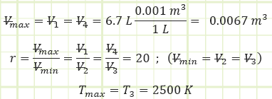
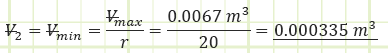
EXAMPLE 1 – 6.7 LITER DIESEL ENGINE Problem statement:
Determine the ideal net work output of a 6.7 liter diesel engine where T3 = 2,500 K and compression ratio is 20. Assume 1 bar(a) and 250 K as ambient conditions.
Given:
Ambient properties:

Engine characteristics:
4-Stroke compression-ignition reciprocating internal combustion.
Find:
1) Net work output of the engine for one cycle.
Assumptions:
1) Air is the working fluid and it behaves like an ideal gas with constant specific heats.
2) The Ideal Diesel Cycle conducted in quasi-equilibrium governs this analysis.
3) The compression and expansion processes are isentropic (adiabatic, reversible); therefore, n = ɣ=cp/cv.
4) The mass of fuel injected is negligible and is modeled as a heat addition.
Solution:
For the naturally-aspirated engine, analyze each process of the Ideal Diesel Cycle and identify unknown properties and/or energy transfers, starting with the completed Intake state (1):

1) Process (1) → (2): Adiabatic Compression:
Use adiabatic relationship for air (k=1.4) to determine absolute pressure at state (2):

Use the value for pressure to find the temperature at state (2) using the Ideal Gas Law:

Determine the boundary work associated with the polytropic process:

2) Process (2) → (3): Isobaric Combustion:
T3 = 2,500 K
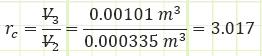
Use ideal gas law to determine the volume at cutoff and the necessary cutoff ratio:

Use the energy correlation for isobaric expansion to determine how much heat was injected during process (2) to (3):

Alternatively, to find Qin:

Use the diesel cycle efficiency correlation to determine Wnet,out:

Source
Unknown Contributor - Reddit
Related:
- Introduction to Thermodynamics, Class 1
- Ideal Gas Assumptions, Properties of Pure Substances, Property Tables, Class 2
- Control Volume Analysis, Reynolds Transport Theorem, Conservation of Mass, and the First, Class 3
- Mechanical Work for Closed Systems Class 4
- Properties of Pure Substances , Phase Changes Class 5
- Thermodynamics of Multiphase Closed Systems Class 6
- Analysis of Open Systems Thermodynamics Class 7
- Introduction to Otto Cycle, Cycle Thermal Efficiency, Spark-Ignition Engine Architecture, and Combustion Cycle Class 8
- FIRST LAW OF THERMODYNAMICS
- SECOND LAW OF THERMODYNAMICS
- Thermodynamic Systems and Surroundings
- Types of Thermodynamic Systems
- Thermodynamic Equilibrium
- Control Volume
- Steady State
- Thermodynamic Process
- Cyclic Process
- Reversible Process
- Irreversible Process
- Adiabatic Process
- Isentropic Process
- Polytropic Process
- Throttling Process
Link to this Webpage:
© Copyright 2000 -
2024, by Engineers Edge, LLC
www.engineersedge.com
All rights reserved
Disclaimer |
Feedback
Advertising
| Contact