Related Resources: thermodynamics
Introduction to Otto Cycle Class 8
Thermodynamics Data, Equations, Charts, Equations and Calculators
Introduction to Otto Cycle, Cycle Thermal Efficiency, Spark-Ignition Engine Architecture, and Combustion Cycle Class 8
Objective(s):
At the completion of the lecture, students should:
1) Understand the working principle of a real internal combustion engine (ICE) operating via spark-ignition (SI).
2) Recognize the approximate P-V cycle of a real SI-ICE engine.
3) Apply thermodynamic processes to approximate the SI-ICE cycle as the Ideal Otto cycle.
4) Identify the importance of the design parameter “Compression ratio” and apply it to the Otto cycle.
5) Be able to calculate the maximum theoretical efficiency of the Ideal Otto Cycle.
6) Understand engine design constraints due to ambient conditions, fuel properties, and engine integrity.
7) Understand using general polytropic processes for the compression and expansion strokes to simulate heat transfer during cold early-startup times and later hot-engine times.
Methodology:
Lecture with animations and video (1, 2) shown via projector. In-class ICE demo unit.
Terminology:
Internally-reversible process: A process in which the contents of a system were changed to state 2, but can be brought back to state 1 following the exact same path such that the new state 1 is exactly the same as the original state 1 and the backward path identically matches the forward path in every aspect except for its direction. Friction is assumed to be nonexistent and the process occurs at quaisi-equilibrium.
Thermodynamic cycle: A series of at least two thermodynamic processes that begin and end at the same state.
Net work output: The sum of all the work output and the necessary work input of the processes making up the cycle. The desired output of the cycle, resulting in useful mechanical work available to the end-user. Also equals the total heat input minus the total heat rejected, i.e. Wnet,out = Qnet,in.
Reciprocating engine: an engine that converts linear motion of a piston into rotary motion of a shaft.
Internal combustion engine (ICE): A device that uses the thermal energy released from the chemical combustion of fuel injected into the control volume to produce useful work or power output.
Spark-ignition (SI): The use of a highly energetic, yet very small energy source to initiate a chemically-exothermic chain reaction within a reactive fuel that otherwise is not hot enough to spontaneously ignite.
Air-to-Fuel ratio: The mass (or molar) ratio of air (which contains oxygen) to fuel. Should be no less than the stoichiometric molar ratio necessary for complete combustion to occur. In practice, it should be significantly greater than the theoretical stoichiometric ratio to ensure every fuel molecule can “find” enough oxygen to undergo complete combustion.
Thermodynamic Cycle: A series of at least two processes in which the system ends up back at its initial state.
Key Ideas:
Real Engines:
Spark-ignition engines are a useful, reliable, lightweight, simple way of converting chemical energy stored in reactive liquid fuels to mechanical work or power in the form of a spinning shaft (or even a giant hammer for driving piles into the ground, although compression-ignition is more-commonly used for this).
Most personal automobiles and small powered watercraft have historically turned to SI ICEs for propulsion.
They come in two main varieties: 4-stroke and 2-stroke.
4-Stroke SI ICEs employ the following four steps to operate:

Figure 1: Credit: Chainsaw Journal
1) Intake stroke. Fresh air enters the combustion chamber through a valve. It can either be naturally “sucked” in by the downward motion of a piston or forced in by an air “charger.” Fuel vapor, either entrained within the intake air by a carburetor or directly injected, also enters the cylinder.
2) Compression stroke. The system becomes closed and the piston rises, compressing the air and fuel to a much smaller volume. The temperature and pressure of the system increases as a result of this work input.
3) Power stroke. At, or near, the point of maximum compression, the air-fuel mixture is ignited by an electric spark. Chemical potential energy is rapidly converted into high-temperature thermal energy, which greatly increases the temperature and pressure within the compressed volume. This increased pressure forces the piston back down, producing a work output. As the piston moves downward, the pressure and temperature decrease.
4) Exhaust stroke. After reaching its lowest point of travel, the piston rises and forces the gaseous combustion products out through an open valve. After the piston has risen as far as it can go, the exhaust valve closes and the intake valve opens. Fresh air is once again ready to be introduced to complete the cycle once again.
Only one stroke of a 4-stroke cycle produces power. The rest of the strokes consume energy via sliding-surface friction and/or gas compression.
When conducting dimensional analysis, revolutions per minute are typically important. It should be noted there
are two revolutions in every full cycle of a 4-stroke ICE. If an engine operates at 2,400 RPM, then there are
(2,400 rev/min)(1/2 cycles/rev) = 1,200 cycles/min = 20 cycles/s = 20 Hz.
2-Stroke SI-ICEs complete the same series of operations, only the strokes are combined. The individual strokes are not as distinctly defined for 2-stroke engines as they are for 4-stroke engines:

1) Intake-and-ignition stroke.
2) Compression-and-exhaust stroke.
2-stroke engines have one power stroke in every two-stroke cycle, making them more powerful on a per-cycle basis. They can be made lighter than 4-stroke engines, but due to design, have historically caused more pollution due to some unburnt fuel escaping during the “scavenging” process that occurs between the exhaust and compression strokes. There is one full cycle for every revolution, so at 2,400 RPM, there are 2,400 cycles/min = 40 cycles/s = 40 Hz.
Design variables:

The SI-ICEs we’re analyzing are of the piston-in-cylinder type. Other types exist, such as the Wankel (i.e. rotary) engine. We need to know the dimensions of the cylinder to figure out the maximum and minimum volume.
Bore: the diameter of the piston within the cylinder.
Stroke: the maximum distance traveled by the piston (i.e. distance between top and bottom dead center).
Clearance volume: the minimum achievable volume of the cylinder; occurs at when piston is Top Dead Center.
Displacement volume: the volume swept out by the piston during a full stroke.
Compression ratio: the ratio between the maximum and minimum achievable volumes.
Mean Effective Pressure: The constant pressure exerted during a work-equivalent expansion from TDC to BDC.
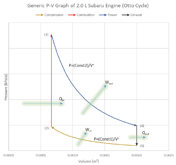
What does the actual SI-ICE cycle look like on a P-V diagram?


What does the ideal Otto cycle look like on a P-V diagram?

Ideal Cycle:
We will analyze the SI-ICE using the Ideal Otto Cycle as our thermodynamic basis for processes:
1) Intake (State 6 to State 1): The volume inside a cylinder isobarically increases from the minimum volume to the maximum volume. The work out of this process will be exactly canceled by the work consumed by the exhaust process. Air is introduced at its ambient properties if the engine is naturally aspirated. If the air is charged, then it will be at a higher pressure and (probably) temperature.
2) Compression (State 1 to State 2): The piston rises, adiabatically compressing the gas (usually air) from its largest volume to its smallest volume. This process requires an input of work. The temperature at any point during this process must remain less than the autoignition temperature of the fuel, to avoid premature ignition (A.K.A. engine “knock”).
3) Ignition (State 1 to State 2): The gas is isochorically heated to its maximum temperature and pressure, one or both of which will be a design constraint. The total combustion occurs instantaneously.
4 Power (State 2 to State 3): The gas adiabatically expands from the minimum volume back to the maximum volume, which yields a work output.
5) Cooling (State 4 to State 5): The gas isochorically cools back to the temperature it was at state 1. These two, (1) and (5), are actually identical states.
6) Exhaust (State 5 to State 6): The gas is isobarically compressed to its smallest volume and the total cycle is completed.
We typically won’t consider the Intake and Exhaust processes in our analyses, since they don’t actually contribute any net heat or work interactions in the overall cycle. We’ll instead focus on the progression from 1 to 2 to 3 to 4 back to 1 (which is identical to 5).

The area bound between the compression & power strokes is the net useful work coming from the cycle:


Tip for consistency: If using a computer program for your calculations, instead of using 1.4 for your value of ɣ, instead use cp/cv = 1.005/0.718. Using 1.4 introduces a little bit of error in the analysis that is easily avoided with cp/cv.
Modifications:
We assumed the compression and expansion (power) processes were perfectly adiabatic and frictionless to simplify the analysis. In actuality they aren’t, and the calculated thermal efficiency represents a theoretical best case scenario.
The “movement processes” (i.e. compression and power/expansion) may be modeled as polytropic processes, instead of adiabatic:
When the engine is cold, the compression process will have a smaller exponent associated with volume, representing a process somewhere between isothermal and adiabatic. The expansion process will have an exponent greater than the specific heat ratio, showing that some of the heat energy injected during the ignition process is being transferred to the engine material as the piston is forced down. The net effect is: it will take less work input to compress the air, but we’ll also be getting less work output during the power stroke, as the cold engine is parasiting some of the energy away.
When the engine is hot, the compression process will have an exponent larger than the specific heat ratio and it will require an input of more work to compress the air as it absorbs heat from the cylinder walls. The expansion process will have an exponent somewhere between adiabatic and isothermal as the expanding air is able to extract some energy from the hot cylinder walls, resulting in slightly more work output, even though less fuel was able to be combusted due to temperature and pressure design constraints of the engine (i.e. State 3 is more-or-less set in stone as a maximum design constraint, and if P2 and T2 are higher than normal due to heat transfer during the compression process, then less heat via fuel can be added, representing a shorter isochoric process line from state 2 hot to 3).
Since either the cold or hot engine scenarios share competing processes within each of their respective cycles, the net effects will tend to cancel out and the adiabatic process is an appropriate approximation. As the onset of ignition is precipitated by a controlled spark within a highly volatile air-fuel mixture, it would technically even be acceptable if the compression process from 1 to 2 cold were perfectly isothermal. This, however, would NOT be acceptable for an engine employing compression to initiate the onset of ignition, and is one of the reasons why real diesel engines have difficulty starting in cold ambient conditions. More on that in future lecture.
For the Otto cycle in this course, we won’t consider non-ideal compression or expansion processes, but it is a phenomenon you may need to be aware of should you ever work on SI ICEs in the future or study them in graduate school.
EXAMPLE 1 – SUBARU GASOLINE ENGINE Problem statement:
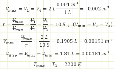
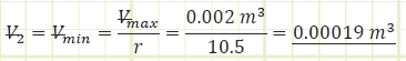
Subaru produces standard 4-stroke gasoline engines of 2.0 L (= Vmax) in size.
Compression ratio of 10.5:1 and a polytropic index of n = 1.4 with current atmospheric conditions of P = 1.01 bar and T = 20 °C. The maximum allowable gas temperature for the engine is 2,200 K.
Given:
Ambient properties:

Engine characteristics:
4-Stroke spark-ignition reciprocating internal combustion.
Find:
1) Determine the power output in horsepower (HP) of the standard engine operating speed of 5,500 rotations per minute (RPM).
2) Determine the cycle efficiency.
Assumptions:
1) Air is the working fluid and it behaves like an ideal gas with constant specific heats.
2) The Ideal Otto Cycle conducted in quasi-equilibrium governs this analysis.
3) The compression and expansion processes are isentropic (adiabatic, reversible); therefore, n = ɣ=cp/cv.
4) The mass of fuel injected is negligible and is modeled as a heat addition.
Diagram:
Solution:
1) For the naturally-aspirated engine, analyze each process of the Ideal Otto Cycle and identify unknown properties and/or energy transfers, starting with the completed Intake state (1):

2) Process (1) → (2): Adiabatic Compression:
Use adiabatic relationship for air (k=1.4) to determine absolute pressure at state (2):

Use the value for pressure to find the temperature at state (2) using the Ideal Gas Law:

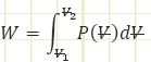
Determine the boundary work associated with the polytropic process:
General Work relation for any process:

Use known work and temperatures to compute the heat transfer associated with the process (for our isentropic process, it should be zero) using the Reynolds Transport Equation (First Law of Thermodynamics):

Simplified Reynold’s EQN for a closed isentropic process (time invariant):

Note: due to an inexact polytropic exponent, some heat transfer into the control volume actually shows up, but it can essentially be disregarded as an erroneous artifact. When n is not equal to ɣ = cp/cv, use the method just shown in order to determine: 1) P2 from the polytropic relationship, 2) T2 from the ideal gas law (if fluid is an ideal gas), and 3) Win from the polytropic work equation, and then 4) find Q(in or out) as the remaining unknown in the Reynolds Transport Equation (i.e. First Law of Thermodynamics: Conservation of Energy). Again, when the process is modeled as isentropic, there should be no heat transfer (or a miniscule amount, as in this case).
3) Process (2) → (3): Isochoric Combustion:
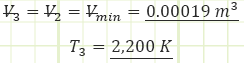
Use temperatures to compute the heat transfer associated with the process:

Use the Ideal Gas Law to determine the absolute pressure at state (3):

4) Process (3) → (4): Isentropic Expansion:


Note: due to an inexact polytropic exponent, some heat transfer out of the control volume actually shows up, but it can essentially be disregarded as an erroneous artifact.
5) Process (4) → (1): Isochoric Cooling (exhaust):

6) Dimensional analysis to determine the power output at 5500 RPM:


Source
Unknown Contributor - Reddit
Related:
- Introduction to Thermodynamics, Class 1
- Ideal Gas Assumptions, Properties of Pure Substances, Property Tables, Class 2
- Control Volume Analysis, Reynolds Transport Theorem, Conservation of Mass, and the First, Class 3
- Mechanical Work for Closed Systems Class 4
- Properties of Pure Substances , Phase Changes Class 5
- Thermodynamics of Multiphase Closed Systems Class 6
- Analysis of Open Systems Thermodynamics Class 7
- FIRST LAW OF THERMODYNAMICS
- SECOND LAW OF THERMODYNAMICS
- Thermodynamic Systems and Surroundings
- Types of Thermodynamic Systems
- Thermodynamic Equilibrium
- Control Volume
- Steady State
- Thermodynamic Process
- Cyclic Process
- Reversible Process
- Irreversible Process
- Adiabatic Process
- Isentropic Process
- Polytropic Process
- Throttling Process
Link to this Webpage:
© Copyright 2000 -
2024, by Engineers Edge, LLC
www.engineersedge.com
All rights reserved
Disclaimer |
Feedback
Advertising
| Contact