Related Resources: thermodynamics
Steady Flow Gas Power Cycles – Brayton Cycle Class 11
Thermodynamics Data, Equations, Charts, Equations and Calculators
Steady Flow Gas Power Cycles – Brayton Cycle Class 11
Objective(s):
At the completion of the lecture, students should:
1) Understand the components and working principles of a real gas turbine system.
2) Apply thermodynamic processes to approximate a gas turbine as the Ideal Brayton cycle.
3) Understand the ideal P-v and T-s cycle diagrams of a simple-cycle gas turbine.
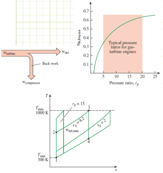
4) Identify the importance of the design parameter “Pressure ratio” with regard to thermal efficiency.
5) Identify the importance of the design parameter Tmax/Tmin with regard to maximum power output.
6) Be able to calculate the maximum theoretical efficiency of the Ideal Brayton Cycle.
7) Understand engine design constraints due to ambient conditions and engine integrity.
8) Apply concept of isentropic efficiency to turbomachinery to estimate performance of an actual gas turbine.
Methodology:
Lecture with animations and video (1,2,3) shown via projector.
Terminology:
Turbomachinery: A machinery component in which subcomponent(s) rotate in order to compress the working fluid or extract energy via the expansion of the working fluid as the fluid steadily flows through them. A spinning pinwheel is a turbine when someone blows on it. A ceiling fan is a very weak compressor when it makes air flow.
Steady Flow: When the working fluid flows through a component at a constant mass flow rate. Its properties may be affected by whatever is happening inside the device via thermodynamic processes.
Steady flow cycle: The working fluid flows from component to component in order to have processes done to it to change its properties. This is in contrast to a closed system, in which the working fluid stays inside one component indefinitely, having its properties change due to that single component either experiencing heat or work interactions at different times in the overall cycle. Steady flow cadet example: On 101st night, the 4/c travel all over the barracks to get grilled by the different cadre in the company wing areas (the cadre are the machinery components, 4/c are the working fluid). Closed system cadet example: Swabs remain stationary on the bulkhead, but get grilled by different cadre members coming to them at different times (swabs are still the working fluid, they just don’t have to run all over the place in order to get worked over by the cadre).
Isentropic efficiency: The degree to which a real component of turbomachinery matches an ideally-isentropic condition. When ηs = 1, the component experiences no internal irreversibilities. When ηs < 1, the component experiences internal irreversibilities that precipitate either more work input (for a compressor) or less work output (for a turbine) in order to achieve the same pressure ratio.
Pressure ratio: The absolute pressure of the air as it’s leaving the compressor divided by the absolute pressure at which it entered to compressor.
Key Ideas:
Real Engines:
Gas turbine heat engines are a useful, reliable, incredibly lightweight, (relatively) simple method of converting chemical energy stored in reactive liquid and gaseous fuels to mechanical work or power in the form of a spinning shaft (power plants) or thrust (aircraft).
Many Naval & USCG vessels currently have gas turbines for propulsion. All USCG aircraft use gas turbines to spin a propeller or rotor to generate thrust. USCGAUX aircraft use reciprocating piston engines (Otto cycle).
They’re one of the most cost-efficient and quick/easy-to-install methods for electrical grid power generation.
Highly scalable & versatile and can burn a wide variety of fuels. Ideally suited for high-performance aircraft for either spinning propeller/fan shaft power and/or raw thrust via exhaust gases.

GE 9HA Harriet, 500,000 BHP = 372,900 kW simple cycle power. When combined with steam cycle, 600 MW!!!
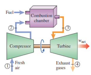
An open-cycle gas turbine engine
The processes of a gas turbine are:
1) Intake (State 1). Ambient air is sucked into a compressor (shown at far left in image above).
2) Compression or pressurization (State 1 to State 2). The air is squeezed as it passes through a compressor. Compressors can be either axial (shown above) or centrifugal. Axial compressors can achieve higher pressure ratios, but they can take up more space. Ideally, the compression is isentropic.
3) Combustion (State 2 to State 3). Fuel is injected into the pressurized air, where it ignites and releases a ton of thermal energy. This is ideally completed isobarically, so temperature goes way up, as does specific volume. The hot gas is ready to expand out of the device, but first it must…
4) Expansion (State 3 to State 4). The hot gases expand as they combust and pass through a turbine. They impinge on the turbine blades, causing it to spin. Some of the shaft’s angular kinetic energy goes forward to keep the compressor spinning, while the rest is used for propulsion or to generate electricity in a generator. Ideally, the expansion takes place isentropically.
5) Exhaust (State 4). The hot expanded gases are expelled from the engine to the ambient environment.
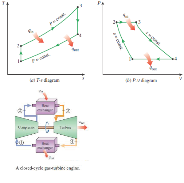
Ideal Brayton Cycle:

The Ideal Brayton Cycle closely mirrors the processes described on the previous page, with these amendments:
1) The ideal cycle is closed in which air is the only working fluid (Air Standard Assumption).
2) Combustion is modeled as isobaric heat addition.
3) Exhaust is modeled as isobaric heat rejection.
It takes a lot of work to compress fluid of relatively large specific volume (such as a gas like air). The proportion of work required by the turbine, as compared to the total work output of the turbine, to run the compressor is called the Back Work Ratio;
![]()
,and it can take a significant chunk of the turbine’s power output.
The efficiency of the cycle (using the Cold Air Assumptions, i.e. constant specific heat & ideal gas behavior) is:

Make it real; isentropic efficiency and pressure drop:
Irreversibilities (friction, viscous losses, ineffective work similar to paddle-wheel heating) occur in the compressor and turbine, hurting their performance. We model this as an isentropic efficiency, which for a compressor is the ratio of isentropic work input against the actual work input (non-ideal compressors always require more work than their ideal counterparts) and for a turbine is the actual work output divided by the isentropic work out (real turbines never give us as much work as ideal ones do).

Some pressure drop in the burner can also occur, which will usually be given as a percentage, i.e. 5% drop in pressure. This means
![]()
EXAMPLE 1 – A SIMPLE CYCLE GAS TURBINE
Problem statement:
A gas-turbine compressor with a pressure ratio of 8 ingests air at 300 K and 100 kPa(a). The turbine inlet maximum temperature is 1,300 K.
Given:

1) T2, T4
2) Back-work ratio
3) Thermal Efficiency Assumptions:
1) Cold Air Standard Assumptions.
2) Turbine exit pressure equals ambient pressure.
3) Isentropic efficiency of turbine and compressor is 100%.
Solution:
Determine state (2) properties from pressure ratio:

Determine state (4) properties from pressure ratio:

Determine turbine and compressor work from First Law:

Steady Flow Gas Power Cycles – Jet Propulsion Cycle
Objective(s):
At the completion of the lecture, students should:
1) Understand the components and working principles of a real jet propulsion turbine engine.
2) Apply thermodynamic processes to approximate a turbojet engine as the Ideal Jet Propulsion Cycle.
3) Recognize the T-s cycle diagram of the Ideal Jet Propulsion Cycle.
4) Understand the purpose of the turbine, diffuser, and nozzle in a real jet engine.
Methodology:
Lecture with animations and video (1,2) shown via projector.
Terminology:
Diffuser: A device that involves no work and (ideally) no heat interactions. Its purpose is to decelerate a highvelocity fluid, converting its kinetic energy into enthalpy (i.e. comes out of a diffuser slower, denser, hotter, and at higher pressure). Modeled as isentropic.
Nozzle: The inverse of a diffuser; it accelerates a fluid by converting some enthalpy into kinetic energy (fluid comes out of a nozzle faster, colder, less dense, and at lower pressure). Involves no work and (ideally) no heat. Produces thrust for an aircraft. Modeled as isentropic.
Turbojet Turbine: Similar to the Brayton Cycle Turbine, but its job is to only produce enough work energy to run the compressor and whatever aircraft auxiliaries are needed. The rest of the fluid’s energy flows through, with thrust being the primary objective.
Thrust: The force imparted to the aircraft via the acceleration of the working fluid through Newton’s Third Law of motion. The time-rate-of-change of the fluid’s momentum is equivalent to the force it exerts as thrust.
Key Ideas:
Real Engines:
Incredibly lightweight and simple (in principle) devices that are easily scalable and produce enough thrust to allow aircraft to fly at least 3+ times the speed of sound (See SR-71 Blackbird).


The Lockheed U-2 Dragonlady, being propelled by a Pratt and Whitney J75 turbojet, flying over my childhood home.
The processes of a turbojet gas turbine are:
1) Intake & deceleration (State 1 to State 2). Ambient air is sucked into a diffuser at high speed and slowed down.
2) Compression or pressurization (State 2 to State 3). The air is squeezed as it passes through a compressor. Ideally, the compression is isentropic.
3) Combustion (State 3 to State 4). Fuel is injected into the pressurized air, where it ignites and releases a ton of thermal energy. This is ideally completed isobarically, so temperature goes way up, as does specific volume.
4) Partial Expansion (State 4 to State 5). The hot gases expand as they combust and pass through a turbine. They impinge on the turbine blades, causing it to spin. Basically all of the shaft’s angular kinetic energy goes forward to keep the compressor spinning. Ideally, the expansion takes place isentropically.
5) Acceleration & exhaust (State 5 to State 6). The hot gases are further expanded & accelerated in a nozzle and then expelled at high speed from the engine, imparting momentum onto the engine and aircraft.
Ideal Jet Propulsion Cycle:

The Ideal Jet Propulsion Cycle closely mirrors the processes described on the previous page, with these amendments:
1) The ideal cycle is closed in which air is the only working fluid (Air Standard Assumption).
2) Combustion is modeled as isobaric heat addition.
3) Exhaust is modeled as isobaric heat rejection.
4) Kinetic energy is significant at States 1 and 6, considered negligible at all other states.
5) The diffuser and nozzle are adiabatic, reversible, and involve no work.
Back Work Ratio;
![]()
for a turbojet is equal to 1, so the turbine work output equals the compressor work input.
The propulsive efficiency of the cycle is:

Make it real; isentropic efficiency and pressure drop:
Irreversibilities occur in the compressor, turbine, diffuser, and nozzle hurting their performance. We model this as an isentropic efficiency, similarly to how it was done for the Brayton Cycle. The nozzle isentropic efficiency formula can be found in Chapter 7. Keep in mind, the actual turbine work output will exactly equal the compressor actual work input. The turbine isentropic work output is still needed in order to find the pressure of the air exiting the turbine, in order to fix the actual properties at the entrance of the nozzle.
Some pressure drop in the burner can also occur, which will usually be given as a percentage, i.e. 5% drop in pressure. This means
![]()
Make it different (and better):
Turbojets aren’t very efficient. Modifications like adding large fans to the front that suck in a send a lot of slow air around the turbojet core are called turbofans (or fanjets) and they’re way more efficient and quieter and pretty much used for all large aircraft that don’t need to fly too crazy fast.
Propjets (or turboprops) have a smaller turbojet engine that spins a propeller.
Ramjets are just plain cool.
Scramjets are the best thing ever. Read about them and try not to be amazed.
EXAMPLE 1 – AN IDEAL TURBOJET ENGINE.
Problem statement:
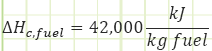
A turbojet aircraft is flying with a velocity of 310 m/s at an altitude of 10,000 m, where the ambient conditions are 29 kPa and -33°C. The pressure ratio across the compressor is 13, and the temperature of the turbine inlet is 1450 K. Air enters the compressor at a rate of 60 kg/s and the jet fuel has a heating value of 42,000 kJ/kg.
Given:
Properties at State (1) [Diffuser intake]:
![Properties at State (1) [Diffuser intake]](/graphics/chap11-20.png)
Properties at State (4) [Turbine inlet]:
![]()
Fuel Characteristics:
Find:
a) The velocity of the exhaust gases [m/s] relative to the aircraft,
b) The thrust developed [kN],
c) The propulsive power developed [kW and HP],
d) The propulsive efficiency,
c) The rate of fuel consumption [kg/s].
Assumptions:
1) Conditions are steady state (i.e. mass, energy, and entropy content of the control volume remains constant) and ideal (no irreversibilities).
2) Air is the sole working fluid and it behaves like an ideal gas with constant specific heats; k=cp/cv.
3) The presence of fuel does not affect mass flow rate or working fluid thermal properties.
4) Kinetic and potential energy is negligible in the compressor (state 2), burner (state 3), and turbine (states 4 and 5), but significant at the diffuser inlet (state 1) and nozzle exit (state 6).
5) The velocity of the air entering the diffuser is the velocity of the aircraft relative to the atmosphere.
Diagram(s):


Solution:
Starting from state (1), analyze the engine sequentially, starting with isentropic deceleration of air in the diffuser, Process (1) → (2):

Process (2) → (3) Isentropic compression of air in a compressor of given pressure ratio:

Process (3) → (4) Isobaric heat addition in a burner:

Process (4) → (5) Isentropic expansion of air in a turbine such that wout,turb=win,comp:

Process (5) → (6) Isentropic acceleration of air in a nozzle:

Net thrust developed, propulsive power, propulsive efficiency, and fuel consumption:

Discussion
It is interesting to note the relative inefficiency of the jet propulsion turbine. Only 27% of the fuel (i.e. 0.331 kg/s) contributes to the propulsion of the aircraft to overcome the effects of drag and keep it at constant velocity (i.e. the aircraft is essentially absorbing the kinetic energy and then shedding it against the effects of drag). Where does the rest of the energy go?
As measured from a stationary point on the ground or a stationary atmosphere (i.e. the aircraft is no longer considered the stationary reference), the kinetic power ejected from the engine is:

32.8% of the heat input shows up as excess kinetic energy (kinetic energy of flowing gases relative to a fixed point on the ground). For the highest propulsive efficiency, the velocity of exhaust gases relative to the ground should be zero (i.e. exhaust gases will flow out of the engine at the same speed as the aircraft, only in the opposite direction, which would only be feasible if no drag force existed).
For energy expelled as excess heat:

40.1% of the heat input shows up as excess thermal energy (enthalpy of the expelled gases). This, the excess kinetic energy, and even the propulsive power dissipated by drag all ultimately become part of the internal energy of the atmosphere.

Source
Unknown Contributor - Reddit
Related:
- Introduction to Thermodynamics, Class 1
- Ideal Gas Assumptions, Properties of Pure Substances, Property Tables, Class 2
- Control Volume Analysis, Reynolds Transport Theorem, Conservation of Mass, and the First, Class 3
- Mechanical Work for Closed Systems Class 4
- Properties of Pure Substances , Phase Changes Class 5
- Thermodynamics of Multiphase Closed Systems Class 6
- Analysis of Open Systems Thermodynamics Class 7
- Introduction to Otto Cycle, Cycle Thermal Efficiency, Spark-Ignition Engine Architecture, and Combustion Cycle Class 8
- Closed System Cycles Ideal & Real Diesel Cycle Class 9
- Closed System Cycles Thermodynamics – Carnot Cycle & Entropy Class 10
- FIRST LAW OF THERMODYNAMICS
- SECOND LAW OF THERMODYNAMICS
- Thermodynamic Systems and Surroundings
- Types of Thermodynamic Systems
- Thermodynamic Equilibrium
- Control Volume
- Steady State
- Thermodynamic Process
- Cyclic Process
- Reversible Process
- Irreversible Process
- Adiabatic Process
- Isentropic Process
- Polytropic Process
- Throttling Process
Link to this Webpage:
© Copyright 2000 -
2024, by Engineers Edge, LLC
www.engineersedge.com
All rights reserved
Disclaimer |
Feedback
Advertising
| Contact