|
||||||||||||
|
||||||||||||
| Radius rod reinforcement | |||
| Post Reply | Forum | ||
| Posted by: atfdmike ® 02/23/2008, 12:26:18 Author Profile eMail author Edit |
Hi, this is my first post on this forum so I wanted to say Hi and then do the usual newbie thing....ask for some help.
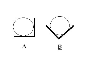
There is a difference of opinion among my friends on which is the better way to reinforce a radius rod on a truck for off road driving. The illustration shows the arrangements. The material for angle iron would be .25" X 1.0. Simply put, which would handle a force directed from the bottom of the diagram towards the top with less chance of deformation? Why? Thanks for looking. Mike
Modified by atfdmike at Sat, Feb 23, 2008, 12:28:23 |
| Post Reply Tell a Friend (must be logged in) Alert Admin About Post |
View All | | Next | |
| Replies to this message |
| : Radius rod reinforcement | |||
| : Radius rod reinforcement -- atfdmike | Post Reply | Top of thread | Forum |
Posted by: randykimball ®  02/24/2008, 00:12:47 Author Profile eMail author Edit |
View a. will be stronger in a vertical or horzontal direction. This is because the vertical and horzontal members of the angle provide more stiffening strength in those directions using the round member to add rigidity from folding those legs. View b. would be better for forces vectored at a 45° direction. However:
The worst suggestion of your lifetime may be the catalyst to the grandest idea of the century, never let suggestions go unsaid nor fail to listen to them. Modified by randykimball at Sun, Feb 24, 2008, 00:26:53 |
| Post Reply Tell a Friend (must be logged in) Alert Admin About Post |
Where am I? Original Top of thread | | | |
| : : Radius rod reinforcement | |||
| : : Radius rod reinforcement -- randykimball | Post Reply | Top of thread | Forum |
| Posted by: jboggs ® 02/24/2008, 17:18:19 Author Profile eMail author Edit |
Also, if weight is an issue at all, you could consider a hollow rod. Material closer to the center of the rod adds little if any to the rod's stiffness. |
| Post Reply Tell a Friend (must be logged in) Alert Admin About Post |
Where am I? Original Top of thread | | | |
| : : : Radius rod reinforcement | |||
| : : : Radius rod reinforcement -- jboggs | Post Reply | Top of thread | Forum |
| Posted by: atfdmike ® 02/25/2008, 06:36:09 Author Profile eMail author Edit |
Thank you for your responses. I made the assumption when I originally posted this question that most of the force would be applied vertically, as the vehicle moved forward towards an obstacle, and the lowest point (or line) would be the bottom of the radius rod.
Based on the answers I received, I am thinking that overbuilding B. by using heavier wall angle iron may cover the range of possible vectors that can occur while off roading. The existing rods are hollow and pretty durable, but have been bent when rock climbing, etc; Thanks again! |
| Post Reply Tell a Friend (must be logged in) Alert Admin About Post |
Where am I? Original Top of thread | | | |
| : : : : Radius rod reinforcement | |||
| : : : : Radius rod reinforcement -- atfdmike | Post Reply | Top of thread | Forum |
| Posted by: CCR5600Design ® 02/25/2008, 10:59:54 Author Profile eMail author Edit |
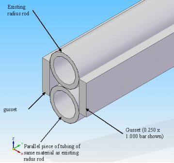
Here is an idea I have personally had experience with. It may or may not work for your application, but I will throw it on the table and see what you think. The tubes will be stitch welded at 4-6 inch intervals and the gussets stitch welded to the pair of tubes at the same interval, but staggered to the welds on the tubing. I hope it helps. Ron
"What we need are more people who specialize in the impossible." - Theodore Roethke Modified by CCR5600Design at Mon, Feb 25, 2008, 11:03:14 |
| Post Reply Tell a Friend (must be logged in) Alert Admin About Post |
Where am I? Original Top of thread | | | |
| : : : : : Radius rod reinforcement | |||
| : : : : : Radius rod reinforcement -- CCR5600Design | Post Reply | Top of thread | Forum |
| Posted by: randykimball ® 02/25/2008, 14:12:51 Author Profile eMail author Edit |
I like that modulas profile,too. If you use this sandwitch configuration you gain strength in many directions without gaining too much unsprung weight considering the gains. The worst suggestion of your lifetime may be the catalyst to the grandest idea of the century, never let suggestions go unsaid nor fail to listen to them. |
| Post Reply Tell a Friend (must be logged in) Alert Admin About Post |
Where am I? Original Top of thread | | | |
| : : : : : : Radius rod reinforcement | |||
| : : : : : : Radius rod reinforcement -- randykimball | Post Reply | Top of thread | Forum |
| Posted by: CCR5600Design ® 02/25/2008, 15:41:01 Author Profile eMail author Edit |
Thanks, Randy. Occasionally, things sink into this thick skull of mine. I learned of this technique from some of my dirt track stock car buddies. It is amazing what these guys can do with a stick welder in 15 minutes! LOL! Ron "What we need are more people who specialize in the impossible." - Theodore Roethke |
| Post Reply Tell a Friend (must be logged in) Alert Admin About Post |
Where am I? Original Top of thread |
Powered by Engineers Edge
© Copyright 2000 - 2024, by Engineers Edge, LLC All rights reserved. Disclaimer