Reciprocating Engine Differential Pressure Compression Check
Power Transmission and Technology Menu
Reciprocating Engine Differential Pressure Compression Check
The differential pressure test is designed to check the compression of reciprocating engines by measuring the leakage through the cylinders caused by worn or damaged components. The operation of the compression tester is based on the principle that, for any given airflow through a fixed orifice, a constant pressure drop across that orifice will result. The restrictor orifice dimensions in the differential pressure tester should be sized for the particular engine as follows:
The orifice size is selected on the following:
- Engines up to 1,000 cubic inch displacement: 0.040 inch orifice diameter, 0.250 inch long, 60-degree approach angle.
- Engines in excess of 1,000 cubic inch displacement: 0.060 inch orifice diameter, 0.250 inch long, 60-degree approach angle.
- As the regulated air pressure is applied to one side of the restrictor orifice with the air valve closed, there will be no leakage on the other side of the orifice and both pressure gauges will read the same. However, when the air valve is opened and leakage through the cylinder increases, the cylinder pressure gauge will record a proportionally lower reading.
- While performing the check the following procedures are listed to outline the principles involved, and are intended to supplement the manufacturer’s instructions for the particular tester being used.
- Perform the compression test as soon as possible after the engine is shut down to ensure that the piston rings, cylinder walls, and other engine parts are well-lubricated.
- Remove the most accessible spark plug from each cylinder.
- With the air valve closed, apply an external source of clean air (approximately 100 to 120 psi) to the tester.
- Install an adapter in the spark plug bushing and connect the compression tester to the cylinder.
- Adjust the pressure regulator to obtain a reading of 20 psi on the regulator pressure gauge. At this time, the cylinder pressure gauge should also register 20 psi.
- Turn the crankshaft, by hand, in the direction of rotation until the piston (in the cylinder being checked) is coming up on its compression stroke. Slowly open the air valve and pressurize the cylinder to 80 psi.
- CAUTION: Care must be exercised in opening the air valve since sufficient air pressure will have built up in the cylinder to cause it to rapidly rotate the propeller if the piston is not at top dead center (TDC).
- Continue rotating the engine
against this pressure until the piston reaches TDC. Reaching TDC is indicated by a flat spot or sudden decrease in force required to turn the crankshaft. If the crankshaft is rotated too far, back up at least one-half revolution and start over again to eliminate the effect of backlash in the valve operating mechanism and to keep piston rings seated on the lower ring lands. - Open the air valve completely. Check the regulated pressure and readjust, if necessary, to read 80 psi.
- Observe the pressure indication of the cylinder pressure gauge. The difference between this pressure and the pressure shown by the regulator pressure gauge is the amount of leakage through the cylinder. A loss in excess of 25 percent of the input air pressure is cause to suspect the cylinder of being defective; however, recheck the readings after operating the engine for at least 3 minutes to allow for sealing of the rings with oil.
- If leakage is still occurring after a recheck, it may be possible to correct a low reading. This is accomplished by placing a fiber drift on the rocker arm directly over the valve stem and tapping the drift several times with a hammer to dislodge any foreign material between the valve face and seat.
- When correcting a low reading in this manner, rotate the propeller so the piston will not be at TDC. This is necessary to prevent the valve from striking the top of the piston in some engines. Rotate the engine before rechecking compression to reseat the valves in the normal manner.
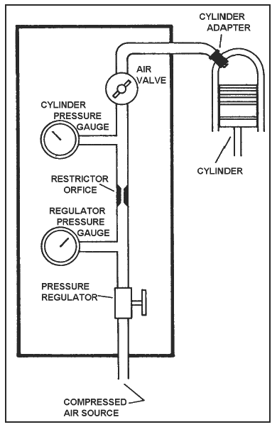
A typical schematic diagram of the
differential pressure tester
Link to this Webpage:
© Copyright 2000 -
2024, by Engineers Edge, LLC
www.engineersedge.com
All rights reserved
Disclaimer |
Feedback
Advertising
| Contact