Related Resources: calculators
Roller Chain Drive Design Calculator and Equations
Power Transmission and Technology
Roller Chain Drive Design Calculator and Equations
Chain design is based on ensuring that the power transmission capacity is within limits for three modes of failure: fatigue, impact, and galling. Chains are designed so that the maximum tensile stress is below the fatigue endurance limit for the finite life of the material. Failure would nevertheless eventually occur but it would be due to wear, not fatigue. In service, failures due to wear can be eliminated by inspection and replacement intervals. When the chain rollers mesh with the sprocket teeth, an impact occurs and a Hertz contact stress occurs, similar to that found for gear meshing. The power rating charts for chain drives limit the selection of the drive so that these modes of failure should not occur, assuming proper installation, operation, and lubrication.
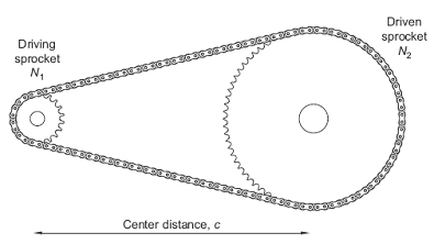
Figure 1 Simple chain drive.
Preview Roller Chain Drive Design Calculator
Chain length, in pitches, is given by
Eq. 1
This formula is approximate, but the error is less than the variation in the length of the best chains. The length L in pitches should be an even number for a roller chain, so that the use of an offset connecting link will not be necessary.
Chain reduction ratios as a function of the standard sprockets available.
where
L = number of pitches,
N1 = number of teeth in the driving sprocket,
N2 = number of teeth in the driven sprocket,
C = center distance (m),
p = chain pitch (m).
The exact center distance is given by
Eq. 2
pitch diameters for the driving and driven sprockets are given by
Eq. 3
Eq. 3a
angle of contact (in radians) between the chain and the sprockets by
Eq. 4
Eq.4a
The chain tension is given by
Eq. 5
Pr = input power (watts)
ω1 = angular velocity of driving sprocket (rad/s)
ω2 = angular velocity of driven sprocket (rad/s).
Number of teeth in the driven sprocket N2 |
Number of teeth in the drive sprocket N1 |
|||||
15 |
17 |
19 |
21 |
23 |
25 |
|
25 |
- |
- |
- |
- |
- |
1.00 |
38 |
2.53 |
2.23 |
2.00 |
1.80 |
1.65 |
1.52 |
57 |
3.80 |
3.35 |
3.00 |
2.71 |
2.48 |
2.28 |
76 |
5.07 |
4.47 |
4.00 |
3.62 |
3.30 |
3.04 |
95 |
6.33 |
5.59 |
5.00 |
4.52 |
4.13 |
3.80 |
114 |
7.60 |
6.70 |
6.00 |
5.43 |
4.96 |
4.56 |
Source: Reproduced from Renold (1996).
Mechanical Design Engineering Handbook
Peter R. N. Childs
2014
Related:
- Roller Chains Review
- Sprocket Chain Length Formulae and Calculator
- Roller Chain Dimensions Table per. ASME/ANSI B29.1M
- Chain Attachments per. ANSI and ASME
- Roller Chain No 41 Horsepower and Speed Ratings
- Single Strand Roller Chain Number 40 Horsepower Ratings Table
- Roller Chains Single Strand No 50 Table
- Horsepower Ratings ANSI Roller Chain No 100 Table
- Horsepower Ratings ANSI Roller Chain No 120 Table
- Single Strand Roller Chain Number 35 Size Table
- Horsepower Ratings ANSI Roller Chain No 80 Table
- Horsepower Ratings Single Strand Roller Chain No 60 Table
- Horsepower Ratings Roller Chain No. 25 Table 1/4 inch
Link to this Webpage:
© Copyright 2000 -
2024, by Engineers Edge, LLC
www.engineersedge.com
All rights reserved
Disclaimer |
Feedback
Advertising
| Contact