Related Resources: calculators
Discharge Rate From Pressurized Tank Equations and Calculator
Civil Engineering Application & Design Resources
Fluids Flow Design and Engineering
Discharge Rate From Pressurized Tank Equations and Calculator
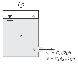
If the gas or vapor above the liquid in a tank is at gage pressure p, and the discharge is to atmospheric pressure, the head causing discharge will be
Eq. 1, SI
Head Pressure
h = z1 - z2 + p / ( ρ · g )
Eq. 1a, U.S.
Head Pressure
h = z1 - z2 + ( p / ρ ) ( gc / g ) = z1 - z2 + p / γ
Preview Discharge From Pressurized Tank Calculator
The discharge velocity can be calculated from Eq. 3 using the increased discharge head calculated from Eq. 1 & 2.
Eq. 2
vo = Cv ( 2 · g · h )0.5
Eq. 3
V = Cd · Ao ( 2 · g · h )0.5
Where
V = volumetric flow rate, ft3/sec, m3/s
Ao = area of discharge orifice, ft2, m2
h = adjusted height / depth of head, ft, m
z1 = elevation of fluid, ft, m
z2 = elevation discharge nozzle, ft, m
g = gravitational acceleration, 32.2 ft/s2, (9.81 m/s2)
gc = gravitational acceleration, 32.2 lbf-ft/lbf-s2, (9.81 kg2/s)
ρ = fluid density lbm/ft3, kg/m3
p = pressure above liquid, lbm/ft2, kg/m2
Cv = coefficient of velocity, empirical factor that accounts for the friction and turbulence at the orifice, see Table 1
Cd = Approximate Orifice Coefficients for Turbulent Water, see Table 1
γ = specific weight of fluid lbf/ft3, N/m3
Figure 1 Discharge from a Pressurized Tank
|
Illustration
|
Description |
Cd
|
Cv
|
|
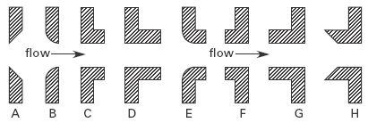
A
|
sharp-edged |
0.62
|
0.98
|
|
B
|
round-edged |
0.98
|
0.98
|
|
C
|
short tube* (fluid separates from walls) |
0.61
|
0.61
|
|
D
|
sharp tube (no separation) |
0.82
|
0.82
|
|
E
|
short tube with rounded entrance |
0.97
|
0.98
|
|
F
|
reentrant tube, length less than one-half of pipe diameter |
0.54
|
0.99
|
|
G r
|
eentrant tube, length 2 to 3 pipe diameters |
0.72
|
0.72
|
|
H
|
Borda |
0.51
|
0.98
|
|
(none)
|
smooth, well-tapered nozzle |
0.98
|
0.99
|
*A short tube has a length less than approximately 3 diameters.
Illustrations for Table 1
Source:
Civil Engineering Reference Manual, Fourteenth Edition
Michael R. Lindeburg, PE
Related
- Fluid Discharged Distance Coordinates Equations and Calculator
- Vertical Tank Draining Time Formulas and Calculator
- Hooghoudt's Drainage Rate Equation and Calculator
- Time to Drain a Conical Tank Equation and Calculator
- Spherical Tank Draining Time Formulas and Calculator
- Horizontal Tank Draining Time Formulas and Calculator
- Orifice Plate Flow Calculations and Design
- Orifice Plate Type Flow Detector Review
- Orifice Submerged in Liquid Discharge Rate Calculator and Equation
- Nozzle Venturi and Orifice Flowmeter Formula and Calculator
- Gas Flow Rate Through Orifice Equations and Calculator per. ISO 5167
- Discharge of Air Through An Orifice Equation and Calculator
- Velocity Escaping Compressed Air Equation and Calculator
- Time to Drain a Conical Tank Equation and Calculator
Link to this Webpage:
© Copyright 2000 -
2024, by Engineers Edge, LLC
www.engineersedge.com
All rights reserved
Disclaimer |
Feedback
Advertising
| Contact