Related Resources: calculators
Non-prestressed Concrete Columns Formulas and Calculator
Civil Engineering Resources
Structural Design Engineering Resources
Nominal Axial Compressive Strength Non-prestressed Concrete Columns per. ACI 318-14 American Concrete Institute (ACI) Formulas and Calculator
The following formulas are taken from the ACI code please note the the associated formulas and calculator may not account for all code variations or requirements.
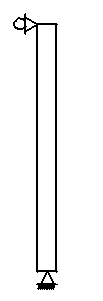
Figure 1
Pinned on bottom Roller all directions top
Load case
Eq. 1
Lc = 1.2 DL + 1.6 LL
For a column with pure axial compression, pinned at the bottom and roller pinned horizontal at top with Load and Resistance Factor Design (LRFD) criteria a
Per. ACI 318-14, paragraph 10.5.1.1, applicable factored load combination,
Eq. 2
(a) Φ Pn ≥ Po
(b) Φ Mn ≥ Po
(c) Φ Vn ≥ Vo
(d) Φ Tn ≥ To
10.5.2.1 Pn and Mn shall be calculated in accordance with 22.4.
ACI 318-14, specifies that the nominal axial compressive strength Pn shall not exceed Pn,max in accordance with Table 1, where Po is calculated by Eq. (x) for nonprestressed members and composite steel and concrete members, and by Eq. (x) for prestressed members.
Table 1, Maximum axial strength (ACI 318-14, Chap. 22, Table 22.4.2.1)
| Member Loading | Transverse reinforcement | Pn,max = |
| Nonrestressed | Ties conforming to | 0.80 Po |
| Spirals conforming to | 0.85 Po |
|
| Prestressed | Ties | 0.80 Po |
| Spirals | 0.85 Po |
|
| Composite steel and concrete columns in accordance to ACI requirements | all | 0.85 Po |
Eq. 3
Pn,max = Table 1
Nominal Axial Compressive Strength for nonprestressed members and composite steel and concrete members, Po
Eq. 4 (ACI 318-14, 22.4.2.2)
Po = [ 0.85 f'c ( Ag - Ast ) + fy Ast ]
Eq. 5
Pn, max = (table 1 ) Po
Pn = Φ Pn, max [ 0.85 f'c ( Ag - Ast ) + fy Ast ]
Action or structural element |
Φ |
Exceptions |
|
(a) |
Moment, axial force, or combined moment and axial force |
0.65 to 0.90 in accordance with 21.2.2 |
Near ends of pretensioned
members where
strands are not fully
developed, ϕ shall be in
accordance with 21.2.3. |
(b) |
Shear |
0.75 |
Additional requirements are given in 21.2.4 for structures designed to resist earthquake effects. |
(c) |
Torsion |
0.75 |
- |
(d) |
Bearing |
0.65 |
- |
(e) |
Post-tensioned anchorage
zones |
0.85 |
- |
(f) |
Brackets and corbels |
||
(f) |
Brackets and corbels |
0.75 |
|
(h) |
Components of connections
of precast members
controlled by yielding of
steel elements in tension |
0.90 |
|
(i) |
Plain concrete elements |
0.60 |
|
(j) |
Anchors in concrete elements |
0.45 to 0.75 in accordance with Chapter 17, ACI 318-14 |
|
Where
Po = nominal axial strength at zero eccentricity, lb
Pnt = nominal axial compressive strength of member, lb
Pnt, max = maximum nominal axial tensile strength of member,
lb
f'c = specified compressive strength of concrete, psi
fy = specified yield strength for nonprestressed reinforcement (steel rebar), psi
fse = effective stress in prestressing reinforcement, after allowance for all prestress losses, psi
Ag = gross area of concrete section, in.2 For a hollow
section, Ag is the area of the concrete only and does
not include the area of the void(s)
Ast = total area of nonprestressed longitudinal reinforcement
including bars or steel shapes, and excluding
prestressing reinforcement, in.2
Apd = total area occupied by duct, sheathing, and
prestressing reinforcement, in.2
Apt = total area of prestressing reinforcement, in.2
Ep = modulus of elasticity of prestressing reinforcement,
psi
DL = Dead load lbsf
LL = live load lbsf
Lc = load case lbsf
Related
- Reinforced Concrete Beam Design to BS8110 Calculator
- Rectangular Concrete Beam and Slab Section Analysis
- Reinforced Concrete Beam Design per. ACI 318-08 Calculator Spreadsheet
- Reinforced Concrete Handbook
Source:
Building Code Requirements for Structural Concrete (ACI 318-08)
Link to this Webpage:
© Copyright 2000 -
2024, by Engineers Edge, LLC
www.engineersedge.com
All rights reserved
Disclaimer |
Feedback
Advertising
| Contact