Related Resources: calculators
Wood Column Stability Factor Formulas and Calculator
Civil Engineering Resources
Structural Design Engineering Resources
Wood Column Stability Factor Formulas and Calculator
The column stability factor is used when designing columns and is applied to the reference compression parallel to the grain design value. If the column is supported throughout its length to prevent lateral displacement in all directions, then CP = 1.0. Otherwise, CP is a function of the column's dimensions, design value in compression and modulus of elasticity as well as other variables.
- When a compression member is supported throughout its length to prevent lateral displacement in all directions, Cp = 1.0.
- The effective column length, le , for a solid column shall be determined in accordance with principles of engineering mechanics - see Eq. 3.
- For solid columns with rectangular cross section, the slenderness ratio, le shall be taken as the larger of the ratios le1 /d1 or le2 /d2 (see Figure 1) where each ratio has been adjusted by the appropriate buckling length coefficient, Ke.
- The slenderness ratio for solid columns, le /d, shall not exceed 50, except that during construction le /d should not exceed 75.
Preview: Wood Column Stability Factor Calculator
The column stability factor shall be calculated as follows:
Eq. 1
Cp = ( 1 + ( FcE / Fc* ) / ( 2 · c ) ) - [ ( ( 1 + ( FcE / Fc* ) / ( 2 · c )2 ) - ( FcE / Fc* ) / c ]0.5
For a rectangular bending member of breadth, b, and depth, d, this becomes:
Eq. 2
FcE = ( 0.822 · Emin' ) / ( le / d )2
Eq. 3
le = Ke · l
Where:
Fc* = reference net bearing area compression design value parallel
to grain multiplied by all applicable adjustment factors except Cp , psi
Emin' = reference and adjusted modulus of
elasticity for beam stability and column
stability calculations, psi
c = 0.8
or sawn lumber
c = 0.85 for round timber poles and piles
c = 0.9 for structural glued laminated timber,
structural composite lumber, and cross-laminated timber
d =
least dimension of rectangular compression member, in.
Ke = Table 1
le =
effective length of compression member,
in.
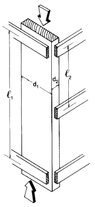
Figure 1 Simple Solid Column
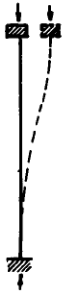
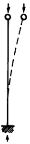
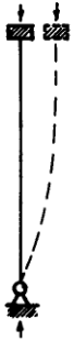
Table 1
| Bucking Configuration |
 |
 |
 |
 |
||
| Theoretical Ke value |
0.5 |
0.7 |
1.0 |
1.0 |
2.0 |
2.0 |
| Recommended design Ke (When ideal conditions approximated) |
0.6 |
0.80 |
1.2 |
1.0 |
2.10 |
2.4 |
| End condition code | Rotation fixed, translation fixed |
|||||
| Rotation free, translation fixed |
||||||
| Rotation fixed, translation free |
||||||
Rotation free, translation free |
||||||
Related
- Ideal Pinned Column Buckling Calculation and Equation
- Steel Beam and Column Analysis and Code Check Calculator
- Buckling Rectangular Column
- Eulers Formula Ideal Pinned Column Buckling Calculator
- Civil Engineering Formulas
- Lag Screws in Wood Pullout Resistance Force Formulae and Calculator
- Pressed Drift Pin Bolts in Wood Force Formulae and Calculator
- Wood Glue Bevel Joint Strength Equations and Calculator
- Commercial Lumber Sizes Chart Table
Source:
National Design Specification for Wood Construction
Link to this Webpage:
© Copyright 2000 -
2024, by Engineers Edge, LLC
www.engineersedge.com
All rights reserved
Disclaimer |
Feedback
Advertising
| Contact