Related Resources: thermodynamics
Steady Flow Vapor Power Cycle – Rankine Cycle w/ Open Feedwater Heating - Class 13
Thermodynamics Data, Equations, Charts, Equations and Calculators
Steady Flow Vapor Power Cycle – Rankine Cycle w/ Open Feedwater Heating - Class 13
Objective(s):
At the completion of the lecture, students should:
1) Understand how to analyze the Rankine Cycle when an open feedwater heater is installed to extract partially-expanded steam from the turbine.
Methodology:
Present an example analysis.
Terminology:
Feedwater Heater: A heat-exchanging device into which feedwater is pumped and partially-expanded steam flows. An open feedwater heater accepts both streams and mixes them and exhibits excellent heat exchange, but both streams must enter at the same pressure; each open feedwater heater in a steam plant must have a dedicated pump associated with it. Closed feedwater heaters are heat exchangers through which both streams flow but do not mix, therefore they can each enter at a different pressure relative to each other; heat exchange is less effective for closed feedwater heaters. The purpose of a feedwater heater is to preheat the feedwater prior to entering the boiler, which reduces the amount of fuel that must be expended to increase the temperature of the feedwater to the boiler outlet temperature. The higher the average temperature of steam is in the boiler, the more efficient the cycle will be. Partially-expanded steam destined for the FWH is bled from the turbine(s) at some intermediate pressure.
How do we use this information?
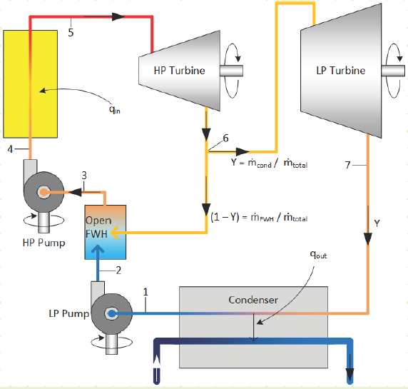
The flow of H2O through the plant is being split, with some partially-expanded steam being sent laterally back to the pre-boiler side to heat the feedwater and the rest being allowed to fully expand through the turbines and subsequently condense in the condenser prior to being pumped, mixed with the bled steam, and then sent to the boiler.

The book uses a slightly different convention than I do; I specify the fraction of steam that’s allowed to fully expand and condense as “Y” and the fraction of bled steam as “(1-Y)”. If you compare the pictures in these lecture notes to the ones in the book, you’ll notice this difference.
Since the streams are being split, we’ll need to keep track of the relative mass flow fractions with regard to turbine and pump work as well as condenser heat rejection and, if there’s boiler reheat, the mass fraction of steam being reheated.
EXAMPLE 1 – REGENERATIVE RANKINE CYCLE WITH OPEN FEEDWATER HEATING AND ISENTROPIC INEFFICIENCIES.
Problem statement:
Power plant operating on Rankine Cycle with given properties and diagram.
Given:
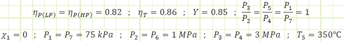
Find:
a) Cycle thermal efficiency.
b) Quality of steam leaving the turbine.
c) Net work output Assumptions:
1) Steady state operations.
2) X Steam is accurate
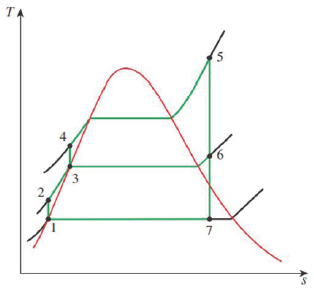
Diagram(s):
Solution:
Determine properties at important stages in the cycle:
Properties at State 1 (Saturated Liquid):

Process 1 → 2s (Isentropic compression in a pump):

Note: the subscript “Y” is there to remind us that this work input is per kilogram of liquid flowing through the pump, but the flow rate is a fraction of the total amount of steam flowing through the HP side of the plant and will need to be multiplied by “Y” during the overall work & heat analysis of the plant.
Process 1 → 2a (Irreversible compression in a pump):

Properties at State 2a (Compressed Liquid):

Properties at State 3 (Unknown Phase):


Note: The open feedwater heater is an adiabatic mixing chamber involving no work, where two streams of different, but related, mass flow rate enter, and the sum of their contributions exit. Conservation of mass requires
![]()
and conservation of energy requires
![]()
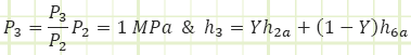
which, when combined with conservation of mass yields
![]()
in which ℎ3 is found to be the mass-weighted average of the enthalpies of the two contributing streams. We therefore need to determine the properties at state 6a to obtain the properties at state 3. The only other state in the cycle for which all properties are easily found is state 5.
Properties at State 5 (Superheated Vapor):

Basis of Turbine Analysis:
Given the more complicated flow regime of this intermediate-bleed turbine, it’s worth evaluating it based on first principles and deriving useful relationships. The diagram for the total turbine, as well as its constituent components, flows, and energy interactions are shown in the diagram below:

For the each section of the turbine, the simplified conservation laws for these steady-state adiabatic devices are:
Mass (HP):

Energy (HP):

Mass (LP):

Energy (LP):


Properties at State 6a (Superheated Vapor):

Process 5 → 6s (Isentropic partial expansion in a turbine):

Process 5 → 6a (Irreversible partial expansion in a turbine):

Properties at State 6a (Superheated Vapor):

Process 2a&6a → 3 (Adiabatic mixing in a feedwater heater):
Now with knowledge of state 6a, we can come back to this process.

Properties at State 3 (Compressed Liquid):

Process 3 → 4s (Isentropic compression in a pump):

Process 3 → 4a (Irreversible compression in a pump):

Properties at State 4a (Compressed Liquid):

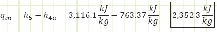
Process 4a → 5 (Heating in a boiler):
Properties at State 7s (Saturated Mixture):

Process 6a → 7s (Isentropic expansion in a turbine):

Process 6a → 7a (Irreversible partial expansion in a turbine):

Properties at State 7a (Saturated Mixture):

Process 7a → 1 (Cooling in a condenser):


Our cycle appears to perform worse than it did when it was analyzed as the Simple Rankine cycle, even though the feedwater heater was supposed to improve efficiency. Of course, for that prior analysis we kept the isentropic efficiencies of the pump and turbine at 1. If this open FWH plant were to be analyzed with ideal isentropic behavior, how does it stack up?

Which is 1.2% better than the 26% observed for the simple plant without a FWH (albeit this modified plant has a lower net power output; 710 kJ/kg for that simple plant vs 642.6 kJ/kg for this one).
What if that ideal simple Rankine plant without a FWH were given the same isentropic efficiency values as this one? Its performance would become:

Finally, what is the effect of turbine pass-through fraction i.e. FWH bleed fraction) vs. plant performance for our plant as given?

If more than 15% of the steam passing through the HP portion of the turbine is bled to the FWH, then the quality at state 3 is greater than 0 and we risk ingesting vapors into the HP pump. Efficiency peaks at this bleed rate, but net work output continues to climb to its maximum value occurring at 0% bleed to FWH.
Can the turbine be analyzed a different, yet equivalent, way? What if we visualize the division of steam occurring immediately after the boiler, with the two streams being sent to two turbines, one that expands (1 - Y ) fraction of the mass flow from P5 to P2 and another that expands Y fraction of the mass flow from P5 to P7?

How does the energy analysis of this alternative concept shake out relative to the one we performed in the main analysis?
For the partial expansion turbine (with steam destined only for the FWH):

![]() (note that this is for every kg actually flowing through it)
(note that this is for every kg actually flowing through it)
So far so good, this is equivalent to what we determined for the HP section of the total turbine.
For the full expansion turbine (with steam destined only for the condenser):
Energy (LP):

![]() (note that this is for every kg actually flowing through it)
(note that this is for every kg actually flowing through it)
This formula is different from the main analysis. Does this make a difference in the overall analysis?
Source
Unknown Contributor - Reddit
Related:
- Introduction to Thermodynamics, Class 1
- Ideal Gas Assumptions, Properties of Pure Substances, Property Tables, Class 2
- Control Volume Analysis, Reynolds Transport Theorem, Conservation of Mass, and the First, Class 3
- Mechanical Work for Closed Systems Class 4
- Properties of Pure Substances , Phase Changes Class 5
- Thermodynamics of Multiphase Closed Systems Class 6
- Analysis of Open Systems Thermodynamics Class 7
- Introduction to Otto Cycle, Cycle Thermal Efficiency, Spark-Ignition Engine Architecture, and Combustion Cycle Class 8
- Closed System Cycles Ideal & Real Diesel Cycle Class 9
- Closed System Cycles Thermodynamics – Carnot Cycle & Entropy Class 10
- Steady Flow Gas Power Cycles – Brayton Cycle Class 11
- Steady Flow Vapor Power Cycles Thermodynamics – Rankine Cycle - Class 12
- FIRST LAW OF THERMODYNAMICS
- SECOND LAW OF THERMODYNAMICS
- Thermodynamic Systems and Surroundings
- Types of Thermodynamic Systems
- Thermodynamic Equilibrium
- Control Volume
- Steady State
- Thermodynamic Process
- Cyclic Process
- Reversible Process
- Irreversible Process
- Adiabatic Process
- Isentropic Process
- Polytropic Process
- Throttling Process
Link to this Webpage:
© Copyright 2000 -
2024, by Engineers Edge, LLC
www.engineersedge.com
All rights reserved
Disclaimer |
Feedback
Advertising
| Contact