Related Resources: gears
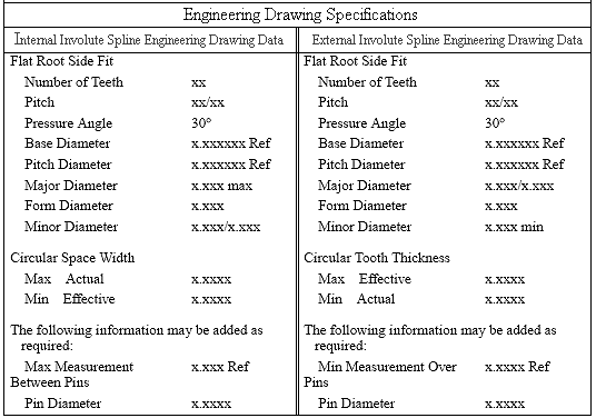
Involute Spline Engineering Drawing Data
 |
|
Table A
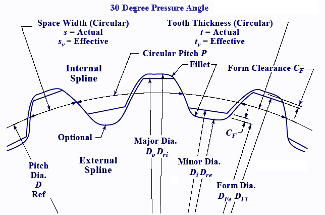
Spline Terms, Symbols, and Drawing Data,
30-Degree Pressure Angle, Flat Root Side Fit ANSI B92.1-1970, R1993 |
Where:
|
cF |
Form Clearance |
|---|---|
| D | Pitch Diameter |
| DFe | Form Diameter, External Spline |
| DFi | Form Diameter, Internal Spline |
| Di | Minor Diameter, Internal Spline |
| Do | Major Diameter, External |
| Dre | Minor Diameter, External Diameter |
| Dri | Major Diameter, Internal Spline |
| s | Actiual Circular Space Width |
|
Sv |
Effective Circular Space Width |
| t | Actual Circular Tooth Thickness |
| tv | Effective Circular Tooth Thickness |

Table B
b) For 15 teeth or less, the minor diameter of the internal spline, unless chamfered, will interfere with the form diameter of the external spline.
c) For 9 teeth or less, the minor diameter of the internal spline, unless chamfered, will interfere with form diameter of the external spline.
d) The internal minor diameter, unless chamfered, will interfere with the external form diameter.
e) The internal minor diameter, unless chamfered, will interfere with the external form diameter.
f) For 10 teeth or less, the minimum chamfer on the major diameter of the external spline may not clear the internal form diameter.
g) Depending upon the pitch of the spline, the minimum chamfer on the major diameter may not clear the internal form diameter.
2) Needed to define a nonfeature datum or basis from which a form or feature is generated.
3) Needed to define a nonfeature dimension from which other specifications or dimensions are developed.
4) Needed to define a nonfeature dimension at which toleranced sizes of a feature are specified.
5) Needed to define a nonfeature dimension from which control tolerances or sizes are developed or added as useful information.
6) Any dimension, specification, or note that is noted "REF" or (REF) should not be used as a criterion for part acceptance or rejection.