Tube and Shell Heat Exchanger Review Review
Heat Exchanger Knowledge | Heat Exchanger Companies Suppliers
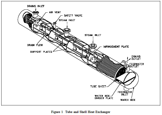
The most basic and the most common type of heat exchanger construction is the tube and shell, as shown in Figure 1. This type of heat exchanger consists of a set of tubes in a container called a shell. The fluid flowing inside the tubes is called the tube side fluid and the fluid flowing on the outside of the tubes is the shell side fluid. At the ends of the tubes, the tube side fluid is separated from the shell side fluid by the tube sheet(s).
The tubes are rolled and press-fitted or welded into the tube sheet to provide a leak tight seal. In systems where the two fluids are at vastly different pressures, the higher pressure fluid is typically directed through the tubes and the lower pressure fluid is circulated on the shell side. This is due to economy, because the heat exchanger tubes can be made to withstand higher pressures than the shell of the heat exchanger for a much lower cost. The support plates shown on Figure 1 also act as baffles to direct the flow of fluid within the shell back and forth across the tubes.
Application and Theory of Operation:
Two fluids, of different starting temperatures, flow through the heat exchanger. One flows through the tubes (the tube side) and the other flows outside the tubes but inside the shell (the shell side). Heat is transferred from one fluid to the other through the tube walls, either from tube side to shell side or vice versa. The fluids can be either liquids or gases on either the shell or the tube side. In order to transfer heat efficiently, a large heat transfer area should be used, leading to the use of many tubes. In this way, waste heat can be put to use. This is an efficient way to conserve energy.
Heat exchangers with only one phase (liquid or gas) on each side can be called one-phase or single-phase heat exchangers. Two-phase heat exchangers can be used to heat a liquid to boil it into a gas (vapor), sometimes called boilers, or cool a vapor to condense it into a liquid (called condensers), with the phase change usually occurring on the shell side. Boilers in steam engine locomotives are typically large, usually cylindrically-shaped shell-and-tube heat exchangers. In large power plants with steam-driven turbines, shell-and-tube surface condensers are used to condense the exhaust steam exiting the turbine into condensate water which is recycled back to be turned into steam in the steam generator.
Engineering Design:
There can be many variations on the shell and tube design. Typically, the ends of each tube are connected to plenums (sometimes called water boxes) through holes in tube sheets.The tubes may be straight or bent in the shape of a U, called U-tubes.
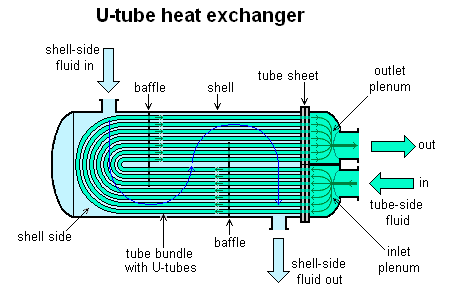
In nuclear power plants called pressurized water reactors, large heat exchangers called steam generators are two-phase, shell-and-tube heat exchangers which typically have U-tubes. They are used to boil water recycled from a surface condenser into steam to drive a turbine to produce power. Most shell-and-tube heat exchangers are either 1, 2, or 4 pass designs on the tube side. This refers to the number of times the fluid in the tubes passes through the fluid in the shell. In a single pass heat exchanger, the fluid goes in one end of each tube and out the other.
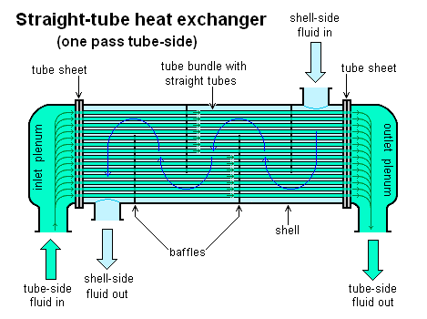
Surface condensers in power plants are often 1-pass straight-tube heat exchangers (see Surface condenser for diagram). Two and four pass designs are common because the fluid can enter and exit on the same side. This makes construction much simpler.
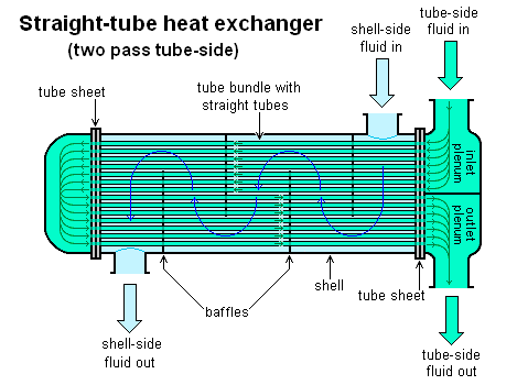
There are often baffles directing flow through the shell side so the fluid does not take a short cut through the shell side leaving ineffective low flow volumes. These are generally attached to the tube bundle rather than the shell in order that the bundle is still removable for maintenance.
Counter current heat exchangers are most efficient because they allow the highest log mean temperature difference between the hot and cold streams. Many companies however do not use single pass heat exchangers because they can break easily in addition to being more expensive to build. Often multiple heat exchangers can be used to simulate the counter current flow of a single large exchanger.
Engineering Materials:
To facilitate to transfer heat well, the tube material should have good thermal conductivity. Because heat is transferred from a hot to a cold side through the tubes, there is a temperature difference through the width of the tubes. Because of the tendency of the tube material to thermally expand differently at various temperatures, thermal stresses occur during operation. This is in addition to any stress from high pressures from the fluids themselves. The tube material also should be compatible with both the shell and tube side fluids for long periods under the operating conditions (temperatures, pressures, pH, etc.) to minimize deterioration such as corrosion. All of these requirements call for careful selection of strong, thermally-conductive, corrosion-resistant, high quality tube materials, typically metals, including copper alloy, stainless steel, carbon steel, non-ferrous copper alloy, Inconel, nickel, Hastelloy and titanium. Poor choice of tube material could result in a leak through a tube between the shell and tube sides causing fluid cross-contamination and possibly loss of pressure.
Link to this Webpage:
© Copyright 2000 -
2024, by Engineers Edge, LLC
www.engineersedge.com
All rights reserved
Disclaimer |
Feedback
Advertising
| Contact