Mohr’s Circle for Plane Stress
Strength / Mechanics of Materials Table of Content
The equations for plane stress transformation have a graphical solution, called Mohr’s circle, which is convenient to use in engineering practice, including “back-of-the-envelope” calculations.
Mohr’s circle is plotted on a coordinate system:
![]()
as in the illustration below, with the center C of the circle always on the:
σ axis at ![]()
The positive τ axis is downward for convenience, to make θ on the element and the corresponding 2θ on the circle agree in sense (both counterclockwise here).
1. The center C of the circle is always on the σ axis, but it may move left and right in a dynamic
loading situation. This should be considered in failure prevention.
2. The radius R of the circle is τmax, and it may change, even pulsate, in dynamic loading. This is
also relevant in failure prevention.
3. Working back and forth between the rectangular element and the circle should be done carefully
and consistently. An angle θ on the element should be represented by 2θ in the corresponding
circle. If τ is positive downward for the circle, the sense of rotation is identical in the element
and the circle.
4. The principal stresses σ1 and σ2 are on the σ axis (τ ).
5. The planes on which σ1 and σ2 act are oriented at 2θpfrom the planes of σx and σy (respectively)
in the circle and at θp in the element.
6. The stresses on an arbitrary plane can be determined by theirσ and τ coordinates from the circle.
These coordinates give magnitudes and signs of the stresses. The physical meaning of +τ vs. –τ regarding material response is normally not as distinct as +σ vs. –σ (tension vs. compression).
7. To plot the circle, either use the calculated center C coordinate and the radius R, or directly plot
the stress coordinates for two mutually perpendicular planes and draw the circle through the two
points (A and B in illustration above) which must be diametrically opposite on the circle.
Related:
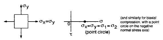
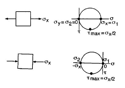
Special Cases of Mohr’s Circles for Plane Stress
|
 |
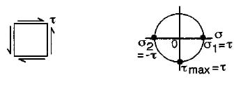 Pure Shear |
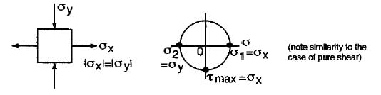 Biaxial tension-compression:
(similar to the case of pure shear). |
Link to this Webpage:
© Copyright 2000 -
2024, by Engineers Edge, LLC
www.engineersedge.com
All rights reserved
Disclaimer |
Feedback
Advertising
| Contact