First Law of Thermodynamics
Thermodynamics Directory | Heat Transfer Directory
First Law of Thermodynamics
The First Law of Thermodynamics is a balance of the various forms of energy as they pertain to the specified thermodynamic system (control volume) being studied.
First Law of Thermodynamics - The First Law of Thermodynamics states:
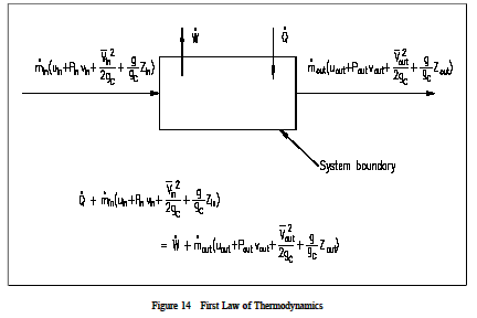
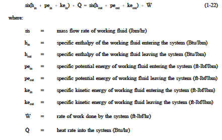
Energy can neither be created nor destroyed, only altered in form. For any system, energy transfer is associated with mass and energy crossing the control boundary, external work and/or heat crossing the boundary, and the change of stored energy within the control volume. The mass flow of fluid is associated with the kinetic, potential, internal, and "flow" energies that affect the overall energy balance of the system. The exchange of external work and/or heat complete the energy balance. The First Law of Thermodynamics is referred to as the Conservation of Energy principle, meaning that energy can neither be created nor destroyed, but rather transformed into various forms as the fluid within the control volume is being studied. The energy balance spoken of here is maintained within the system being studied. The system is a region in space (control volume) through which the fluid passes. The various energies associated with the fluid are then observed as they cross the boundaries of the system and the balance is made. As discussed in previous chapters of this module, a system may be one of three types: isolated, closed, or open. The open system, the most general of the three, indicates that mass, heat, and external work are allowed to cross the control boundary. The balance is expressed in words as: all energies into the system are equal to all energies leaving the system plus the change in storage of energies within the system. Recall that energy in thermodynamic systems is composed of kinetic energy (KE), potential energy (PE), internal energy (U), and flow energy (PL); as well as heat and work processes. Σ (all energies in) = Σ (all energies out) + Δ(energy stored in system) ![]() For most industrial plant applications that most frequently use cycles, there is no change in storage (i.e. heat exchangers do not swell while in operation). In equation form, the balance appears as indicated on Figure 14.
For most industrial plant applications that most frequently use cycles, there is no change in storage (i.e. heat exchangers do not swell while in operation). In equation form, the balance appears as indicated on Figure 14.
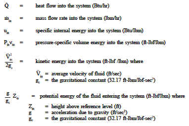
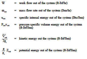
where:
Heat and/or work can be directed in to or out of the control volume. But, for convenience and as a standard convention, the net energy exchange is presented here with the net heat exchange assumed to be into the system and the net work assumed to be out of the system. If no mass crosses the boundary, but work and/or heat do, then the system is referred to as a "closed" system. If mass, work and heat do not cross the boundary (that is, the only energy exchanges taking place are within the system), then the system is referred to as an isolated system. Isolated and closed systems are nothing more than specialized cases of the open system. In this text, the open system approach to the First Law of Thermodynamics will be emphasized because it is more general. Also, almost all practical applications of the first law require an open system analysis.
An understanding of the control volume concept is essential in analyzing a thermodynamic problem or constructing an energy balance. Two basic approaches exist in studying Thermodynamics: the control mass approach and the control volume approach. The former is referred to as the Le Grange approach and the latter as the Eulerian approach. In the control mass concept, a "clump" of fluid is studied with its associated energies. The analyzer "rides" with the clump wherever it goes, keeping a balance of all energies affecting the clump.
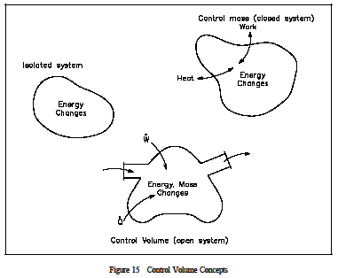
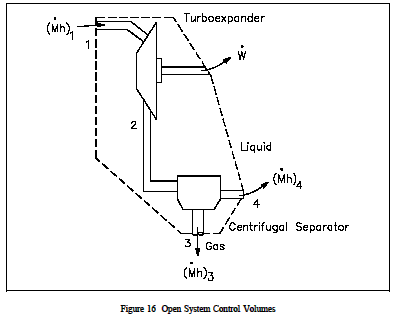
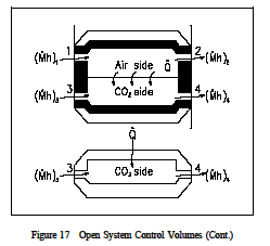
The control volume approach is one in which a fixed region in space is established with specified control boundaries, as shown in Figure 15. The energies that cross the boundary of this control volume, including those with the mass crossing the boundary, are then studied and the balance performed. The control volume approach is usually used today in analyzing thermodynamic systems. It is more convenient and requires much less work in keeping track of the energy balances. Examples of control volume applications are included in Figures 16-18.
The forms of energy that may cross the control volume boundary include those associated with the mass (m) crossing the boundary. Mass in motion has potential (PE), kinetic (KE), and internal energy (U). In addition, since the flow is normally supplied with some driving power (a pump for example), there is another form of energy associated with the fluid caused by its pressure. This form of energy is referred to as flow energy (Pν-work). The thermodynamic terms thus representing the various forms of energy crossing the control boundary with the mass are given as m (u + Pν + ke + pe).
In open system analysis, the u and Pν terms occur so frequently that another property, enthalpy, has been defined as h=u+Pν. This results in the above expression being written as m (h + ke + pe). In addition to the mass and its energies, externally applied work (W), usually designated as shaft work, is another form of energy that may cross the system boundary.
In order to complete and satisfy the conservation of energy relationship, energy that is caused by neither mass nor shaft work is classified as heat energy (Q). Then we can describe the relationship in equation form as follows.
Example 1 illustrates the use of the control volume concept while solving a first law problem involving most of the energy terms mentioned previously.
Example 1: Open System Control Volume
The enthalpies of steam entering and leaving a steam turbine are 1349 Btu/lbm and 1100 Btu/lbm, respectively. The estimated heat loss is 5 Btu/lbm of steam. The flow enters the turbine at 164 ft/sec at a point 6.5 ft above the discharge and leaves the turbine at 262 ft/sec. Determine the work of the turbine.
Solution:

This example demonstrates that potential and kinetic energy terms are in significant for a turbine, since the delta(ape) and delta(kea) values are less than 1 Btu/lbm. When the system (the fluid being studied) changes its properties (temperature, pressure, volume) from one value to another as a consequence of work or heat or internal energy exchange, then it is said that the fluid has gone through a "process." In some processes, the relationships between pressure, temperature, and volume are specified as the fluid goes from one thermodynamic state to an other. The most common processes are those in which the temperature, pressure, or volume is held constant during the process. These would be classified as isothermal, isobaric, or isovolumetric processes, respectively. Iso means "constant or one." If the fluid passes through various processes and then eventually returns to the same state it began with, the system is said to have undergone a cyclic process. One such cyclic process used is the Rankine cycle, two examples of which are shown in Figure 19. The processes that comprise the cycle are described below.
ab: Liquid is compressed with no change in entropy (by ideal pump).
bc: Constant pressure transfer of heat in the boiler. Heat is added to the compressed liquid, two-phase, and super heat states.
cd: Constant entropy expansion with shaft work output (in ideal turbine).
da: Constant pressure transfer of heat in the sink. Unavailable heat is rejected to the heat sink (condenser).
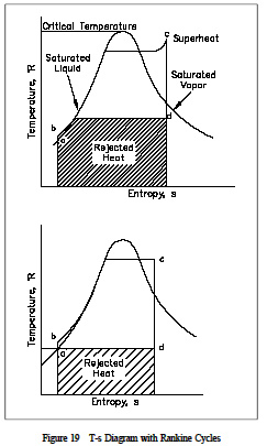
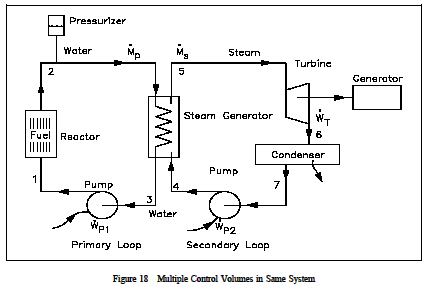
Note the individual processes the fluid must go through before completing the complete cycle. Rankine cycles will be discussed in greater detail later in this module. Figure 20 shows a typical steam plant cycle. Heat is supplied to the steam generator (boiler) where liquid is converted to steam or vapor. The vapor is then expanded adiabatically in the turbine to produce a work output. Vapor leaving the turbine then enters the condenser where heat is removed and the vapor is condensed into the liquid state. The condensation process is the heat-rejection mechanism for the cycle. Saturated liquid is delivered to the condensate pump and then the feed pump where its pressure is raised to the saturation pressure corresponding to the steam generator temperature, and the high pressure liquid is delivered to the steam generator where the cycle repeats itself.
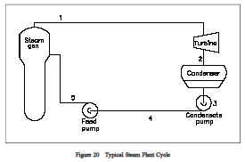
With the example complete, it seems appropriate to discuss the various components of a typical steam plant system. Although such a system is extremely complex, only the major components will be discussed. A typical steam plant system consists of: a heat source to produce the thermal energy (e.g. nuclear or fossil fuel); a steam generator to change the thermal energy into steam energy (a complete steam plant usually exists in connection with the steam generator in converting the steam into eventual electrical energy); pumps to transfer the fluid back to the heat source (reactor coolant pumps in a nuclear reactor); a pressurizer to ensure that the primary system maintains its desired pressure; and the necessary piping to ensure the fluid passes through each stage of its cyclic process. Of necessity, the steam plant is a large "closed" system. However, each component of the system is thermodynamically analyzed as an open system as the fluid passes through it. Of primary importance is the process of dissipating the energy created by the heat source. This process takes place in the steam generator, which acts as a giant two-phase heat generator.
The hot fluid from the heat source passes through the primary side of the steam generator where its energy is passed to the secondary side of the heat exchanger in such a manner as to create steam. The fluid, with its energy removed from the primary side, leaves the steam generator at a lower temperature, and is pumped back to the heat source to be "re-heated." Each major component of a steam plant can be treated as a separate open system problem. A thermodynamic analysis, using the various forms of energies discussed, can be applied to the particular component in studying its behavior. A simplified example of the thermodynamics involved in the steam generator is shown below.
Example 2: Open System -Steam Plant Component
Primary fluid enters the heat exchanger of a nuclear facility at 610°F and leaves at 540°F. The flow rate is approximately 1.38 x 10⁸ lbm/hr. If the specific heat of the fluid is taken as 1.5 Btu/lbm°F, what is the heat transferred out of the steam generator?
Solution:
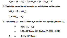
The minus sign indicating heat out of the heat exchanger, which is consistent with the physical case. This example demonstrates that for a heat exchanger, the heat transfer rate
can be calculated using the equation
![]()
. It is important to note that the later equation can only be used when no phase change occurs since ΔT = 0 during a phase change. The first equation can be used for a phase change heat transfer process as well as for latent heat calculations.
The pumps used for returning the fluid to the heat source can be analyzed as a thermodynamic system also. One such example is illustrated in Example 3.
Example 3: Open System -Coolant
A power pump is used to return the fluid from the heat exchanger back to the core. The flow rate through the pump is about 3.0 x 10⁷ lbm/hr with the fluid entering the pump as saturated liquid at 540°F. The pressure rise across the pump is 90 psia. What is the work of the pump, neglecting heat losses and changes in potential and kinetic energy?
Solution:
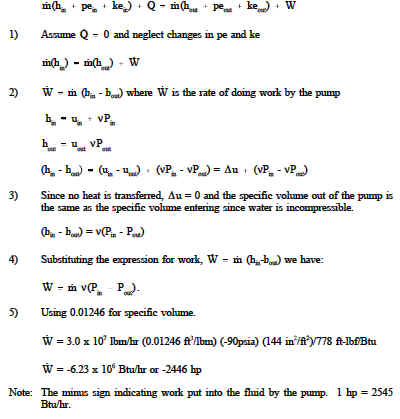
Note: The minus sign indicating work put into the fluid by the pump. 1 hp = 2545 Btu/hr.
A thermodynamic balance across the reactor core gives an indication of the amount of heat removed by the coolant that is given off by the fuel rods.
Example 4: Thermodynamic Balance across Heat Source
In a particular facility, the temperature leaving the reactor core is 612°F, while that entering the core is 542°F. The coolant flow through the heat source is 1.32 x 10⁸ lbm/hr. The cp of the fluid averages 1.47 Btu/lbm°F. How much heat is being removed from the heat source? The pe and ke energies are small compared to other terms and may be neglected.
Solution:
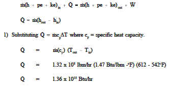
For this example ![]() has been used to calculate the heat transfer rate since no ˙
has been used to calculate the heat transfer rate since no ˙
phase change has occurred. However, Qm (hout-hin) could also have been used had
the problem data included inlet and outlet enthalpies.
The individual principal components of a reactor system have been thermodynamically analyzed. If all components were combined into an overall system, the system could be analyzed as a "closed" system problem. Such an analysis is illustrated in the following example.
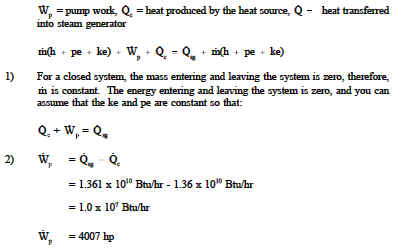
Example 5: Overall Thermodynamic Balance
A nuclear facility (primary side) is to be studied as a complete system. The heat produced by the heat source is 1.36 x 10¹⁰ Btu/hr. The heat removed by the heat exchanger (steam generator) is 1.361 x 10¹⁰ Btu/hr. What is the required pump power to maintain a stable temperature?
Solution:
Of the examples just completed, emphasis should be placed on the heat exchanger analysis. Both the primary side and the secondary side have their own energy balances as the heat energy is transferred from one fluid to the other. In calculating heat exchanger heat transfer rates, we found that we could use the equations ![]()
Perhaps a short analysis of the secondary side of the heat exchanger will aid in understanding the heat exchanger’s importance in the energy conversion process.
Example 6: Secondary Side of Heat Exchanger
Steam flows through a condenser at 2.0 x 10⁶ kg/hr, entering as saturated vapor at 40°C (h = 2574 kj/kg), and leaving at the same pressure as sub cooled liquid at 30°C (h = 125.8 kJ/kg). Cooling water is available at 18°C (h = 75.6 kJ/kg). Environmental requirements limit the exit temperature to 25°C (h = 104.9 kJ/kg). Determine the required cooling water flow rate.
Solution:
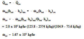
In this example, we calculated the flow rate using the equation Q= mΔh since a phase change occurred when the steam was condensed to liquid water. Q p ˙
mc ΔT would not have worked ˙since ΔT=0 for a phase change. Had we attempted to solve the problem using Q p=mc ΔT, we
˙would have discovered that an error occurs since the ΔT=10oC is the ΔT needed to subcool the liquid from saturation at 40oC to a subcooled value of 30oC. Therefore, the heat transfer process to condense the steam to a saturated liquid has not been taken into account.
Link to this Webpage:
© Copyright 2000 -
2024, by Engineers Edge, LLC
www.engineersedge.com
All rights reserved
Disclaimer |
Feedback
Advertising
| Contact