When the natural frequency of a rotating (i.e., dynamic) structure, such as a bearing or a rotor assembly in a fan, is energized, the rotating machine element resonates. This phenomenon is called dynamic resonance and the rotor speed at which it occurs is the critical speed.
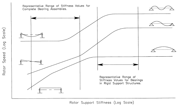
Figure 1 illustrates a typical critical speed, or dynamic resonance, plot. The graph shows the relationship between rotor-support stiffness (X-axis) and rotor speed (Yaxis). Rotor-support stiffness depends on the geometry of the rotating element (i.e., shaft and rotor) and the bearing-support structure. These are the two dominant factors that determine the response characteristics of the rotor assembly.
Figure 1
In most cases, running speed is the forcing function that excites the natural frequency of the dynamic component. As a result, rotating equipment is designed to operate at primary rotor speeds that do not coincide with the rotor assembly's natural frequencies. As with static components, dynamic machine components have one or more natural frequencies that can be excited by an energy source that coincides with, or is in proximity to, that frequency.
High amplitudes of the rotor's natural frequency are strictly speed dependent. If the frequency of the energy source, in this case speed, changes to a value outside the resonant zone, the abnormal vibration disappears.
As with static resonance, the actual natural frequencies of dynamic members depend on the mass, bearing span, shaft and bearing-support stiffness, freedom of movement, and other factors that define the response characteristics of the rotor assembly (i.e., rotor dynamics) under various operating conditions.
In most cases, dynamic resonance appears at the fundamental running speed or one of the harmonics of the excited rotating element. However, it also can occur at other frequencies. For example, a rotor assembly with a natural frequency of 1800 rpm cannot operate at speeds between 1980 and 1620 rpm (+/- 10%) without the possibility of exciting the rotor's natural frequency.
Most low- to moderate-speed machinery is designed to operate below the first critical speed of the rotor assembly. Higher speed machines may be designed to operate between the first and second, or second and third, critical speeds of the rotor assembly. As these machines accelerate through the resonant zones or critical speeds, their natural frequency is momentarily excited. As long as the ramp rate limits the duration of excitation, this mode of operation is acceptable. However, care must be taken to ensure that the transition time through the resonant zone is as short as possible.
Note that critical speed should not be confused with the mode shape of a rotating shaft. Deflection of the shaft from its true centerline (i.e., mode shape) elevates the vibration amplitude and generates dominant vibration frequencies at the rotor's fundamental and harmonics of the running speed.
However, the amplitude of these frequency components tends to be much lower than those caused by operating at a critical speed of the rotor assembly. Also, the excessive vibration amplitude generated by operating at a critical speed disappears when the speed is changed, but those caused by mode shape tend to remain through a much wider speed range or may even be independent of speed.
Confirmation Analysis:
In most cases, the occurrence of dynamic resonance can be quickly confirmed. When monitoring phase and amplitude, resonance is indicated by a 180-degree phase shift as the rotor passes through the resonant zone. Figure 2 illustrates a dynamic resonance at 500 rpm, which shows a dramatic amplitude increase in the frequencydomain display. Resonance is confirmed by the 180-degree phase shift in the timedomain plot. Note that the peak at 1200 rpm is not resonance. The absence of a phase shift, coupled with the apparent modulations in the FFT, eliminates the possibility that this peak is resonance related.
Figure 2
Common Confusions:
Vibration vibration profiles that tend to coincide with the fundamental (1x) running speed or one or more of the harmanalysts often confuse resonance with other failure modes. Many of the common failure modes tend to create abnormally high vibration levels that appear to be related to a speed change. Therefore, analysts tend to miss the root cause of these problems.
Dynamic resonance generates abnormal onics. This often leads the analyst to incorrectly diagnose the problem as imbalance or misalignment.