Related Resources: calculators
Helical Gears Shafts Parallel Center Distance Approximate Design Equations and Calculator
Machine Design and Engineering
Mechanical Gear Design and Engineering
Helical Gears Shafts Parallel, Center Distance Approximate Design Equations and Calculator
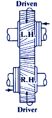
Determining Helix Angles.—The following rules should be observed for helical gears with shafts at any given angle. If each helix angle is less than the shaft angle, then the sum of the helix angles of the two gears will equal the angle between the shafts, and the helix angle is of the same hand for both gears; if the helix angle of one of the gears is larger than the shaft angle, then the difference between the helix angles of the two gears will be equal to the shaft angle, and the gears will be of opposite hand.
Pitch of Cutter to be Used.—The thickness of the cutter at the pitchline for cutting helical gears should equal one-half the normal circular pitch. The normal pitch varies with the helix angle, hence, the helix angle must be considered when selecting a cutter. The cutter should be of the same pitch as the normal diametral pitch of the gear. This normal pitch is found by dividing the transverse diametral pitch of the gear by the cosine of the helix angle. To illustrate, if the pitch diameter of a helical gear is 6.718 and there are 38 teeth having a helix angle of 45 degrees, the transverse diametral pitch equals 38 divided by 6.718 = 5.656; then the normal diametral pitch equals 5.656 divided by 0.707 = 8. A cutter, then, of 8 diametral pitch is the one to use for this particular gear.
Helical gears should preferably be cut on a generating-type gear cutting machine such as a hobber or shaper. Milling machines are used in some shops when hobbers or shapers are not available or when single, replacement gears are being made. In such instances, the pitch of the formed cutter used in milling a helical gear must not only conform to the normal diametral pitch of the gear, but the cutter number must also be determined.
Preview Helical Gears Shafts Parallel, Center Distance Approximate Design Calculator
Pitch diameter of large gear formula
D = N / ( Pn cos α )
Pitch diameter of small gear formula
d = n / ( Pn cos α )
Outside diameter of large gear
O = D + 2 / Pn
Outside diameter of small gear
o = d + 2 / Pn
Number of teeth marked on formed milling cutter (large gear)
T = N / cos3α
Number of teeth marked on formed milling cutter (small gear)
t = n / cos3α
Lead of helix on large gear
L = π D cot α
Lead of helix on small gear
l = πd cot α
Center distance (if not right, vary α)
C = 1⁄2 (D + d)
Where:
D = Pitch diameter of large gear (in, mm),
d = Pitch diameter of small gear (in, mm),
L = Lead of helix on large gear (in, mm),
l = Lead of helix on small gear (in, mm),
C = approximate center distance (in, mm),
Pn = normal diametral pitch (in, mm),
N = number of teeth in large gear
n = number of teeth in small gear
α = angle of helix (deg.)
T = Number of teeth
References:
Machinerys Handbook, 29th Edition
Link to this Webpage:
© Copyright 2000 -
2024, by Engineers Edge, LLC
www.engineersedge.com
All rights reserved
Disclaimer |
Feedback
Advertising
| Contact