Related Resources: calculators
Internal Combustion Engine Flywheel To Drive Machine Formula and Calculator
Machine Design Engineering and Design
Internal Combustion Engine Flywheel To Drive Machine Formula and Calculator
The torque (T ) delivered by an internal combustion engine is a function of the rotation angle (θ). In fact, for a four-stroke engine, power is delivered during only one of the four 180◦ cycles. For the other three cycles, the inertia and thermodynamic processes of the system are slowing the engine down. If the engine has only one cylinder, the variation in torque, and therefore, the power, is greater than if the engine has multiple cylinders, say six or eight, each delivering power at different rotation angles. However, the design of the flywheel for this type of engine, whatever the number of cylinders, is the same.
A graph of the torque (T ) versus rotation angle (θ) for one cycle of a four-stroke, single cylinder, internal combustion engine is shown in Fig. 1.
There are several important quantities to note in Fig. 1. First, the mean torque (Tm) is the average torque over the total angle of rotation, balancing the areas under the curve above and below the zero torque line. For a four-stroke engine the total angle of rotation (φ) is 2 revolutions, or 720◦, or 4π rad, whereas for a two-stroke engine the total angle of rotation (φ) is 1 revolution, or 360◦, or 2π rad.
Second, the minimum angular velocity (ωmin) occurs at the start of the power cycle and the maximum angular velocity (ωmax) occurs at the end of the power cycle. The engine slows down from the angle of rotation for maximum angular velocity to the angle of rotation that starts the next power cycle. Also, whenever the torque curve passes through the mean torque line, the system has zero angular acceleration, which means it has the mean angular velocity (ωm).
Third, the work done on the system to increase its speed from the minimum angular velocity to the maximum angular velocity is the area of the shaded region shown. It is determined once the mean torque (Tm) has been found, usually graphically, from the relationship in Eq. 1
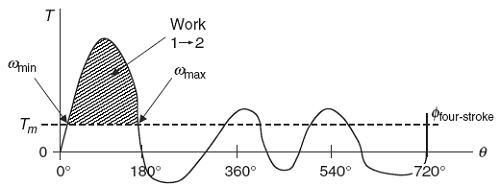
Figure 1
Torque as a function of rotation angle α
Preview Inertial Energy and Angular Acceleration of a Flywheel Calculator
Internal Combustion Engine Flywheel Equations
Eq 1
Work 1→2 = Tm φ
where (φ) is the total angle of rotation for one cycle of the engine.
The work done can be related to the angular velocities and the inertia of the system by modifying Eq. 2
Eq. 2
Work 1→2 = 0.5 Isys ( ω2max - ω2min )
The difference in the squares of the angular velocities in Eq. 2 can be expressed algebraically as the product of two terms as follows:.
Work 1→2 = 0.5 Isys ( ω2max - ω2min )
Work 1→2 = 0.5 Isys ( ωmax + ωmin ) ( ωmax - ωmin )
Work 1→2 = Isys ( ωmax + ωmin )/2 ( ωmax - ωmin )
Thus Eq. 3
Work 1→2 = Isys ωo ( ωmax - ωmin )
where ωo is not the mean or average angular velocity (ωm) as the torque curve is not symmetrical about the horizontal axis.
coefficient of speed fluctuation (Cf) is defined as:
Cf = ( ωmax - ωmin ) / ωm
substituting into the expression for the work done
Work 1→2 = Isys ωo ( ωmax - ωmin )
we get
Eq. 4
Work 1→2 = Isys ωo ( Cf ωm )
Most designs call for a small coefficient of fluctuation (Cf ), which means the angular velocity (ωo) will be approximately equal to the mean angular velocity (ωm). Therefore,
Work 1→2 = Isys ωo ( Cf ωm )
Thus Eq. 5
Work 1→2 = Isys ( Cf ω2m )
Solving for the mass moment of inertia of the system (Isys) in Eq. 5, and substituting for the work done in terms of the mean torque (Tm) and the total angle of rotation (φ) from
Isys = Work 1→2 / ( Cf ω2m )
Eq. 6
Isys = ( Tm φ ) / ( Cf ω2m )
Note that while it is desired to keep the coefficient of fluctuation (Cf) as small as possible, it would take an infinite mass moment of inertia in the system to make it zero. Therefore, the system will always have some variation in angualar velocity.
The mean torque (Tm) and mean angular velocity (ωm) are related to the power (P) delivered by the engine. The power (P), measured experimentally, is usually given at a specific angular velocity in revolutions per minute (rpm). The relationship between power, mean torque, and mean angular velocity is given as,
Eq. 7
P = Tm ωm
Solving for the mean torque (Tm) gives
Eq. 8
Tm = P / ωm
Once the mean torque (Tm) is found from Eq. 8, rather than graphically, over a total angle of rotation (φ) for one cycle, and using the given mean angular velocity (ωm) and the desired coefficient of fluctuation (Cf ), the required mass moment of the system (Isys) can be determined from Eq. 6.
Converting rpm to rad/s
Eq. 7
rad / sec = rpm * (2 π /rev ) * 1 min / 60 s
Declarations:
Isys = mass moment of inertia of the system (slug · ft2, kg · m2 ),
ω1, 2, m = angular velocity (rad/s),
P = Power (HP),
Cf = coefficient of fluctuation (%),
φ = total angle of rotation (radians),
Tm = mean torque ft · lbs, N · m)
Related:
- Thin Wall Shaft Mass Moment of Inertia
- Tangent Drive Motor Mass Moment of Inertia Equation
- Estimated Motor and Transmission Inertia and Drive Requirements
- Solid Cylinder Mass Moment of Inertia Equation and Calculator
- Gear Drive Motor Mass Moment of Inertia Equation
- Direct Drive Motor - Load Mass Moment of Inertia Equation
- General Equation and Calculator Mass Moment of Inertia
Source:
Mark's Calculations for Machine Design
Thomas H. Brown, Jr.
Faculty Associate
Institute for Transportation Research and Education
NC State University
Raleigh, North Carolina
Link to this Webpage:
© Copyright 2000 -
2024, by Engineers Edge, LLC
www.engineersedge.com
All rights reserved
Disclaimer |
Feedback
Advertising
| Contact