Related Resources: calculators
Pipe Bends Minimum Wall Thickness Calculator per. ASME B31.3
Fluids Flow Design and Engineering
Hydraulic & Pneumatic Design Engineering
Pipe Bends Minimum Wall Thickness Design Calculator per. ASME B31.3
Thickness variations from the intrados to the extrados and along the length of the bend shall be gradual for curved and mitered segments of pipe.
Preview Pipe Bends Minimum Wall Thickness Design Calculator
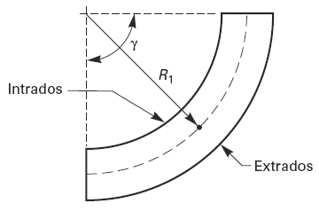
Figure 1, Nomenclature Pipe Bend
The minimum required wall thickness, tm of a bend, after bending, in its finished form, shall be determined as follows:
Eq. 1
t = P · D / ( 2 [ ( S · E · W / I ) + P · Y ] )
Eq. 2 Intrados (inside bend radius)
IInt = [ 4 · ( R1 / D ) -1 ] / [ 4 ( R1 / D ) - 2 ]
Eq. 3 Extrados (outside bend radius)
IExt = [ 4 · ( R1 / D ) +1 ] / [ 4 ( R1 / D ) + 2 ]
Table 1, Values of Coefficient Y for t < D / 6
| Material | Temperature, °C (°F) |
|||||||
482 (900) and below |
510 (950) |
538 (1,000) |
566 (1,050) |
593 (1,100) |
621 (1,150) |
649 (1,200) |
677 (1250) and above |
|
| Ferric Steels | 0.4 |
0.5 |
0.7 |
0.7 |
0.7 |
0.7 |
0.7 |
0.7 |
| Austenitic steels | 0.4 |
0.4 |
0.4 |
0.4 |
0.5 |
0.7 |
0.7 |
0.7 |
| Nickel alloys | 0.4 |
0.4 |
0.4 |
0.4 |
0.4 |
0.7 |
0.5 |
0.7 |
| Gray iron | 0.0 |
- |
- |
- |
- |
- |
- |
- |
| Other ductile metals | 0.4 |
0.4 |
0.4 |
0.4 |
0.4 |
0.4 |
0.4 |
0.4 |
Where:
P = internal design gage pressure
D = Outside diameter of pipe
R1 = pipe center line radius
S = Stress value for material
E = quality factor, typically 0.8, ranging from 0.6 - 1.0
W = Weld joint strength reduction factor, typically 1.0
I = Intrados Eq. 2 or Extrados Eq. 3
Y = coefficient from table 1
Thickness variations from the intrados to the extrados and along the length of the bend are gradual.The thickness requirements apply at the mid-span of the bend, γ / 2, at the intrados, extrados, and the bend center line radius.
Source:
- ANSI ASME B31.3 Process Piping, Page 50
Related:
- Schedule 40 Pipe Dimensions
- Schedule 80 Pipe Dimensions
- Hydrostatic Pressure Force of a Fluid On Vessel Planes Equations The hydrostatic force of pressure F is that force which is exerted on the wall by the fluid only - i.e. without consideration of pressure
- Vessel With Pressure Applied to Liquid Level Equations and Calculator
- Thin-Walled Cylinders of Cast Iron With Internal Pressure Formula and Calculator
- Thick-walled Cylinders of Ductile Material, Open Ends Birnie's Formula and Calculator
- Partially Full Pipe Flow Calculator Determines the Flow within a partially full pipe using the Manning equation.
- Hydrostatic Pressure vs Depth Liquid Table Chart Hydrostatic Pressure vs Depth Water Table Chart and Equation
- API Casing 5.500 - 6.625 Dia. Engineering Data Table API Casing Data Tables sizes 5.50 - 6.625.
- API Casing 6.625 - 7.000 Dia. Engineering Data Table API Casing Data Tables sizes 6.625 - 7.000 Dia.
- API Casing 7.000 - 7.625 Dia. Engineering Data Table API Casing 7.000 - 7.625 Dia. Table
- API Casing 7.625 Dia. Engineering Data Table API Casing 7.625 Dia. Table
- API Casing 7.625 - 8.625 Dia. Engineering Data Table API Casing 7.625 - 8.625 Dia. Table
- Design for Pipe and Tube Forming Premium Membership Required
- Lames Equation Thick-walled Cylinders of Brittle Material, Ends Open or Closed Formula and Calculator
- Pipe Friction Calculations Within Pipe For Fluid Flow Pipe Friction drives the pipe size requirements within a fluid flow system and is dependant on the piping system design requirements.
Link to this Webpage:
© Copyright 2000 -
2024, by Engineers Edge, LLC
www.engineersedge.com
All rights reserved
Disclaimer |
Feedback
Advertising
| Contact