Related Resources: Electrical Electronics Excel Calculators
AC Grounding Requirements Calculator Spreadsheet
NOTE: Refunds are not awarded after excel files have been downloaded - review your membership agreement for details.
Electronics and Electrical Design and Engineering
Civil Engineering and Design
AC Substation Grounding Requirements Calculator Spreadsheet
Note: Accessing this resource requires an active Premium Membership with Engineers Edge
Download: AC Substation Grounding Requirements Calculator Spreadsheet
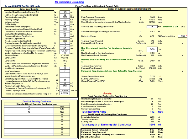
As per. IEEE Std. 80-1986
Design Details
Length of Area Occupied by Earthing Grid
Width of Area Occupied by Earthing Grid
Fault level at Incoming Bus
Incoming Voltage
Outgoing Voltage
Soil Resistivity
Resistance of Main Eartjing Mat
Resistance of surface Material (Crushed Rock )
Thickness of Surface Material (Crushed Rock)
Depth of Earthing Grid Conductor
Diameter of Earthing Grid Conductor
Reference Depth of Grid
Area Occupied by Earthing Grid
Spacing between Parallel Conductor of Grid
Duration of Fault (To determine Size of earthing Mat)
Duration of Fault (To determine safe Step & Touch Potential)
Margine Factor in Earthing Mat against corrossion and Rusting
Number of Adjacement Earthing Mat Conductor
Relaction Factor
Constant (KS)
Constant (Ki)
Number of Parallel Conductor in Longitudinal direction
Number of Parallel Conductor in Transverse direction
No of Lighting Arrestors
No of Transformers
Decrement Factor for entire duration of Fault(to allow asymetrical of the Fault curernt wave)
Results:
No of Earthing Rod used at perimeter
Extra Earthing Rod used at 4 coners of Earthing Mat
Earth Electrode for Lighting Arrestors
Eatrh Electode for Transformer
Control Room Earthing
Total Earthing Rods
Total Length of Earthing Mat Conductor
Longitudinal direction
Transverse direction
Earthing Rod
Total Length of Eartning Mat Conductor
Estimated Touch Potential
Estimated Step Potential
Estimated Length of Earthing Mat Conductor
No of Earthing Rod
Corrective projection factor according for the relative increase fault current during S/S life( Zero future system growth Cp=1)
Ambient Temperature
Maximum allowable Temperature
Temperature of Thermal Co-efficient of resisitivty at 0°C
Thermal Capacity Factor
Thermal Co-efficient of resistiivty at referance Temp of Tr
The intent of this calculator is to provide information pertinent to safe grounding practices in ac substation design. The specific purposes of this calculator are to:
a) Establish, as a basis for design, the safe limits of potential differences that can exist in a substation under fault conditions between points that can be contacted by the human body.
b) Review substation grounding practices with special reference to safety, and develop criteria for a safe design.
c) Provide a procedure for the design of practical grounding systems, based on these criteria.
d) Develop analytical methods as an aid in the understanding and solution of typical gradient problems.
Unless proper precautions are taken in design, the maximum potential gradients along the earth's surface may be of sufficient magnitude during ground fault conditions to endanger a person in the area. Moreover, dangerous voltages may develop between grounded structures or equipment frames and the nearby earth.
a) Relatively high fault current to ground in relation to the area of ground system and its resistance to remote earth.
b) Soil resistivity and distribution of ground currents such that high potential gradients may occur at points at the earth's surface.
c) Presence of an individual at such a point, time, and position that the body is bridging two points of high potential difference.
d) Absence of sufficient contact resistance or other series resistance to limit current through the body to a safe value under circumstances a) through c).
e) Duration of the fault and body contact, and hence, of the flow of current through a human body for a sufficient time to cause harm at the given current intensity
Link to this Webpage:
© Copyright 2000 -
2024, by Engineers Edge, LLC
www.engineersedge.com
All rights reserved
Disclaimer |
Feedback
Advertising
| Contact