GD&T Fixed Fastener Condition Projected Tolerance Zone Compensation
Tolerances, Engineering Design & Limits & Fits
(This calculator requires a java - enabled browser)
This calculator calculates position tolerances utilizing principles and concepts withinASME Y14.5-2009, ASME Y14.5M - 1994 and ASME Y14.5-2018, Geometric Dimensioning and Tolerancing (GD&T).
Open:
GD&T Fixed Fastener Condition Projected Tolerance Zone Compensation Calculator
This calculator will calculate the required field compensating for the effects of the fastener projection. Calculations assume a line-line case at tolerance and feature-of-size maximum departure.
Note: All fields require an input except field being calculated.
Four (5) inputs are required.
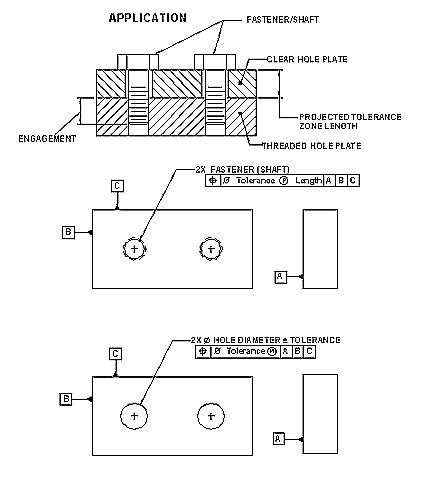
See the application illustration at bottom of page.
The following are definitions for the elements:
Fastener (Shaft) Diameter - This is the maximum size (MMC) of the bolt, shaft or other feature of size.
Hole Diameter - This is the smallest hole (MMC) for the given feature of size.
Fastener (Shaft) Tolerance - The positional tolerance of the installed bolt, screw or shaft.
Hole Tolerance - This is the clearance hole positional tolerance @ MMC.
Projected Tolerance Zone - This is the distance that the fastener (shaft) extends beyond the hole which it is installed within. This compensates for the effects of the shaft distance. (Projected tolerance zone is very important when significant shaft length must be compensated for.
Thread or Shaft Engagement - This is the minimum distance of fastener or shaft engagement into the fixed component.
Open:
GD&T Fixed Fastener Condition Projected Tolerance Zone Compensation Calculator
Related Resources:
- True Position GD&T Tolerance Calculator
- Tolerance Calculator Floating Fastener Condition
- Tolerance Calculator Fixed Fastener Condition
- Tolerance Calculator 2 Mating Features @ MMC
- Tolerance Calculator 3 Mating Features @MMC
- Tolerance Calculator - True Position
- Tolerance Calculator - Spherical True Position
- Hole / Feature Pattern Plot
- GD&T Geometric Dimensioning Tolerancing Basics Training
- GD&T Geometric Dimensioning Tolerancing Intermediate Training
- GDT ASME Y14.5-2009 Applications Training
- G&T Geometric Tolerancing ISO 1101 Training
- Online GD&T Fundamentals Training
