Pneumatic Actuator Controller Design and Operation
Hydraulic and Pneumatic Knowledge
[ Previous Page ] [ Article Start ]
Pneumatic Actuator Controller Design and Operation
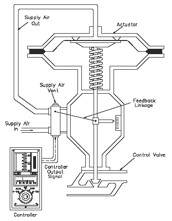
The controller generates an output signal that represents the demanded position. This signal is sent to the positioner. Externally, the positioner consists of an input connection for the control signal, a supply air input connection, a supply air output connection, a supply air vent connection, and a feedback linkage. Internally, it contains an intricate network of electrical transducers, air lines, valves, linkages, and necessary adjustments. Other positioners may also provide controls for local valve positioning and gauges to indicate supply air pressure and control air pressure (for pneumatic controllers). From an operators viewpoint, a description of complex internal workings of a positioner is not needed. Therefore, this discussion will be limited to inputs to and outputs from the positioner.
In Figure F2, the controller responds to a deviation of a controlled variable from setpoint and varies the control output signal accordingly to correct the deviation. The control output signal is sent to the positioner, which responds by increasing or decreasing the supply air to the actuator. Positioning of the actuator and control valve is fed back to the positioner through the feedback linkage. When the valve has reached the position demanded by the controller, the positioner stops the change in supply air pressure and holds the valve at the new position. This, in turn, corrects the controlled variables deviation from setpoint.

Figure F2
Related:
- Piston Type Fluid Accumulator - General Design
- Spring Type Fluid Accumulator - General Design
- Schedule 40 Steel Pipe Sizes & Dimensions ANSI
- Hydraulic Cylinder Piston Velocity
- Hydraulic, General
- Hydraulic Head Pressure
- Hydrostatic Pressure vs Depth Liquid Table Chart
- Velocity and Flow Capacity of Oil Standard Tubes
- Velocity and Flow Capacity of Oil Schedule 40 Pipe
- Velocity and Flow Capacity of Oil Schedule 80 Pipe
- Velocity and Flow Capacity of Oil Schedule 160 Pipe