Related Resources: Electrical Electronics Excel Calculators
NCP5222 Design Tool Calculator Spreadsheet
NOTE:
- Refunds are not awarded after excel files have been downloaded - review your membership agreement for details.
- This excel spreadsheet may contain macros which will need to be enabled in your excel application, see web page: Enable macros in Downloaded excel files
- Units utilized within calculators are either SI or Imperial (some enable both SI and Imperial) and member (you) are responsible for conversions. Ensure that you verify units utilized in excel application meet your requirements before downloading.
Electrical and Electronics Design, Engineering Resources
Engineering Excel Spreadsheet Downloads
NCP5222 Design Tool Calculator Spreadsheet
Note: Accessing this resource requires an active Premium Membership with Engineers Edge
Download: NCP5222 Design Tool Calculators
Description
The NCP5222, a fast-transient-response and high-efficiency dual-channel / two-phase buck controller with built-in gate drivers, provides multifunctional power solutions for notebook power system. This Excel spreadsheet is a design aid for applications with the NCP5222 operating in 2-Phase mode, in which a bridge MOSFET is employed to connect the two output power rails. There are two functions provided by this design aid. The first function is to come up with a recommended solution after the user inputs an application spec; The second function is to work out calculation results based on user's real application solution and operation condition. (For NCP5222 2-channel applications, please refer to the other design aid -- "NCP5222 Design Aid (2-Channel Mode)")
How to use?
1. Application Spec Input (Sheet "Summary")
- Input supply nominal voltage (Cell "G12") and range (Cell "G14" and "G15"). The range is within 4.5V ~ 27V.
- Output voltage nominal values (Cell "C22") and acceptable voltage deviation percentage (Cell "I24") in Vo2.
- Output current noninal values (Cell "C30" and "I30"), and over current ratio numbers (Cell "C31" and "I31").
Note: The over current ratio may be fine tuned to optimize power split between the two phases. - Inductor current ripple spec (Cell "C47" and "I47") and output voltage ripple/transient spec (Cell "C49:C53" and "I49:I53").
- Load transient current spec (Cell "C58:C61" and "I58:I61").
- Ambient temperature in Cell "C65".
2. Component Selection (Sheet "Summary", "System Configuration", and "MOSFET Database")
- Select inductors according to recommended values (Cell "C106" and "I106" in Sheet "Summary"), and input information of the selected inductors in Cell "Q31:T31" and "Q69:T69" of Sheet "System Configuration".
- Select output capacitors according to recommended total capacitance (Cell "C109" and "I109" in Sheet "Summary") and effecitive ESR (Cell "C110" and "I110" in Sheet "Summary"), and input information of the selected capacitors in Cell "V29:X29, V31" and "V67:X67, V69" of Sheet "System Configuration".
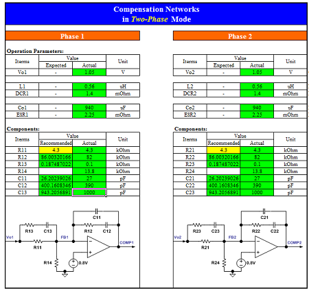
- Select feedback and compensation components in Cell "J124:J130, D125:D126, D128:D130" of Sheet "Summary", according to recommended parameters in Cell "I124:I130, C125:C126, C128:C130" of Sheet "Summary".
- Select current-sensing netwoks in Cell "D116:D118, J116:J118" of Sheet "Summary", according to recommended parameters in Cell "C116:C118, I116:I118" of Sheet "Summary".
- Input parameters of selected power MOSFETs, schottky diode (if used), and bridge MOSFET in Sheet "System Configuration".
- Input snubbers (if used) in Cell "C93:C94" and "I93:I94" of Sheet "Summary".
- Input on-board BST and/or gate resistance (if used) in Cell "D98:D100" and "J98:J100" of Sheet "Summary".
3. Review Calculation Results (Sheet "Summary", "Compensation", and "Loss & Efficiency")
- 1) Review inductor current ripple, output ripple, and transient performance in Sheet "Summary".
- Input loading current of the two output power rails in Cell "D30" and "J30" of Sheet "Summary" to review power sharing and loss in the two phases under this loading condition.
- Review current sharing and OCP trip points in Sheet "Summary".
- Review output regulation and close-loop gain/phase in Sheet "Compensation".
- After set ambient temperature in Cell "G65" of Sheet "Summary", make the predicted temperatures (Cell "B71:D71, F71, H71:J71") of the components to be close to the calculated results (Cell "B70:D70, F70, H70:J70" in Sheet "Summary") in order to improve calculation accuracy.
- Review power losses, temperatures, and efficiency details in Sheet "Loss & Efficiency".
4. Fine Tune Solution (Sheet "Summary" and "System Configuration")
Optimize solution by repeating action Item 2 and Item 3.
5. Record Design and Print Out Schematic (Sheet "Summary" and "Schematic")
Link to this Webpage:
© Copyright 2000 -
2024, by Engineers Edge, LLC
www.engineersedge.com
All rights reserved
Disclaimer |
Feedback
Advertising
| Contact